![]()
Engine and Drive Train
Although compression tests looked good, it was clear that the engine, transmission, and differential hadn't been opened for quite a while, so this clearly was the time to check them out. There were plenty of external indications of things that needed to be sorted, such as incorrect head studs, missing or broken screws and nuts, and so on. It was no surprise that I found more as I dug into those components.
Click on any picture to see a larger version in a new window.
Contents
- Engine and Transmission Removal
- Engine
- Clutch and Flywheel
- Transmission and Overdrive
- Drive Shaft
- Rear Axles
- Rear Axle Case and Differential
- Engine and Transmission Reinstallation
- Engine Start Up
- Completed Chassis and Drive Train
- Rear Wheel Stud Replacement
- Rear Hub Remover
Engine and Transmission Removal
Once the body was removed, access to the engine was easy. Because so much had already been removed, only a few bolts held the engine and transmission to the frame. Both were easy to remove.
I decided to remove the transmission and engine separately. I first drained the oil from both, noting happily that there was no metal in it. The engine was then supported by a jack, the transmission bolts at the mount and bell housing were removed, and the drive shaft was disconnected. The transmission could then be separated and lifted. In the past, I have been able to lift a TR4A transmission without a crane, but this one has an overdrive, so it's heavier, and I haven't been 18 for about half a century.
I noticed several problems. First, the drive shaft bolts were quite loose; that's scary. Second, many of the bolts were wrong: the transmission mount had one 7/16-inch bolt, with a strange head size, instead of the requisite 1/2-inch, and some of the bell housing bolts were much too short. I also noticed a loose upper shock-absorber bushing and incorrect shock hardware. All these will be fixed, of course, but they illustrate one of my adages about restoring old cars: check everything, and don't assume that anything is OK.
![]()
![]()
![]()
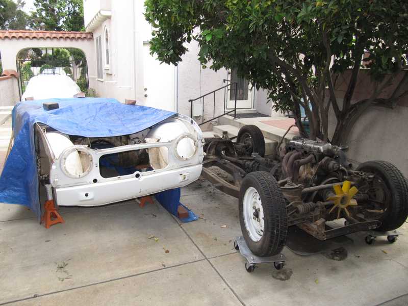
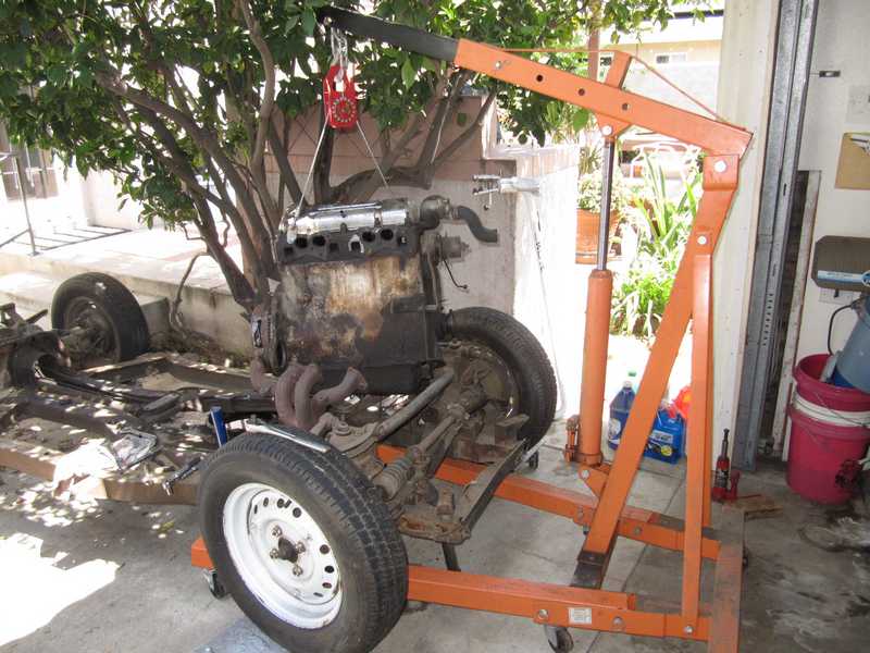
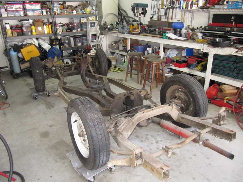
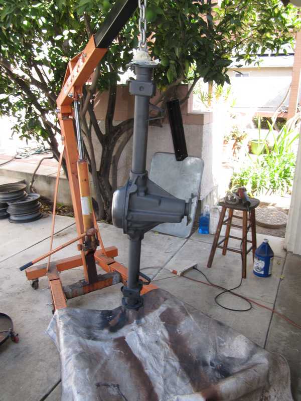
Next came the engine. I removed the last couple of bolts holding it into the chassis, removed its fan and pedestal, and lifted it out easily. The engine and transmission waited for attention, sitting on the floor in a corner of the garage.
![]()
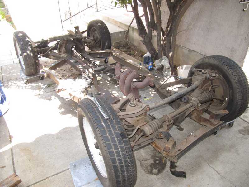
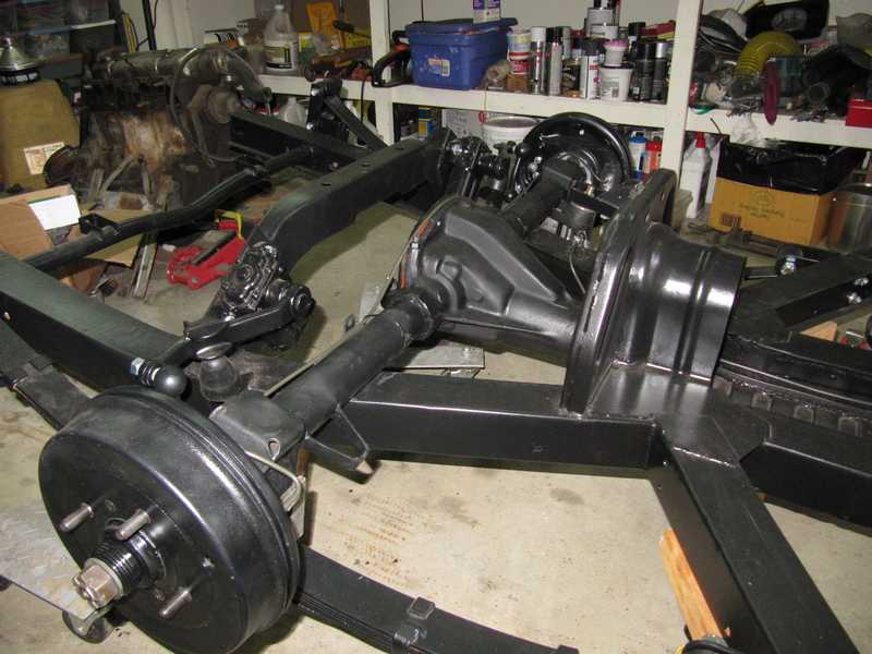
I moved the chassis into the garage, where I could work on it more easily. That also left more room in the driveway for the body.
Engine
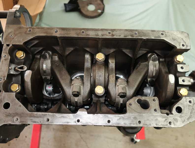
I didn't measure the cylinder compressions, but they were reportedly good. Even so, the engine's age dictated that it should at least be opened and inspected. I found a lot of problems, including broken piston rings and many other parts that were well worn, so I decided to do a complete rebuild.
A full description of the engine work can be found on the Engine page.
Clutch and Flywheel
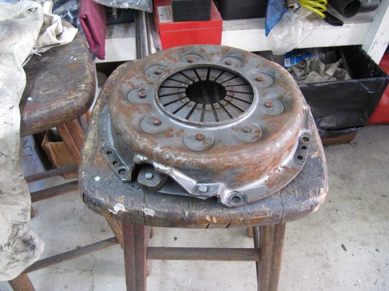
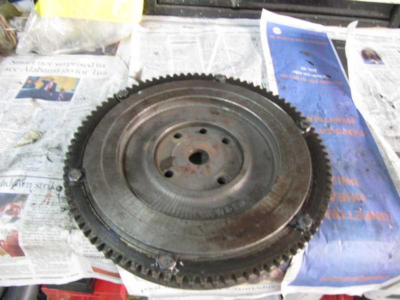
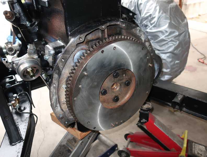
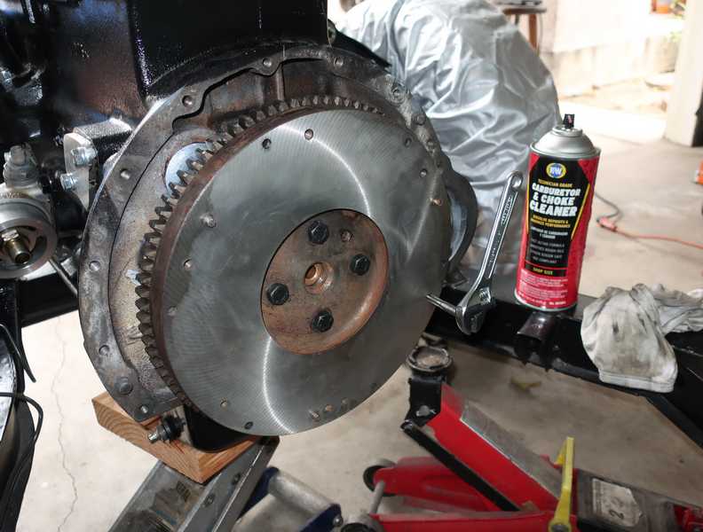
Once the transmission and engine were separated, I couldn't resist taking a quick look at the clutch and flywheel. They confirmed my car-restoration motto, stated previously: don't assume that anything is OK. The first thing I noticed was a tooth missing from the ring gear. A little surprising, as the other teeth looked pretty good. It seemed clear that there would be a new ring gear in my future.
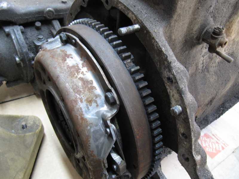
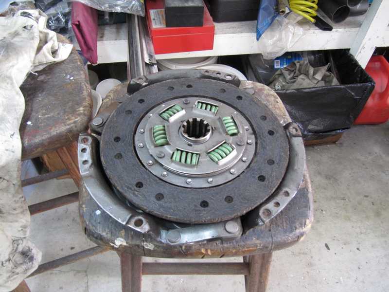
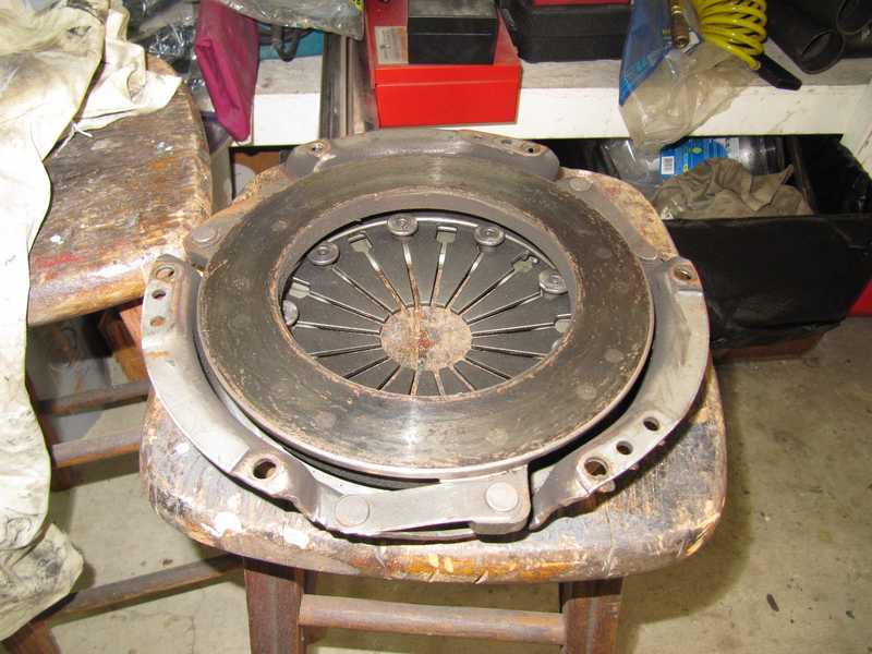
There was a lot of oily gunk in the bell housing, which often means that there is a lot of oily gunk on the clutch.This one looked surprisingly clean. The disk was lightly worn; the rust on the pressure-plate housing showed that it had been around awhile, but the lack of wear on the fingers indicated that it was not used much. If this was a budget restoration, I could have sanded the disk lightly and reused this clutch, but this wasn't a budget restoration, and clutch kits for this car are not expensive. I replaced it.
Replacing the ring gear was straightforward. Although it is bolted onto the flywheel, the ring gear is an interference fit, but not as tight as those that are shrunk onto a flywheel. I put a little oil on it and used a set of long bolts to press it into place. I then replaced those bolts with the originals. The bolts are held in place by tabbed washers, and I also applied nonpermanent thread locker. (I have subsequently stopped using tabbed washers in favor of thread locker, Belleville washers, and Nord-Lock washers.)
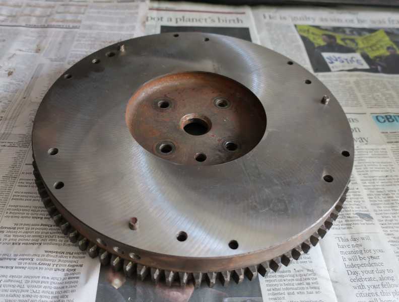
I had the flywheel balanced and resurfaced. You can see three drill holes in the edge, where metal was removed for balancing.
Installing the flywheel and clutch requires some care; it doesn't take much imagination to figure out why.
First, the pilot bearing. It was a rather tight fit, so I used a puller (in reverse!) to press it into place. I was afraid that tapping it in with a hammer, however gently, might damage it. It's just a sintered bronze bearing, not known for toughness. Per the usual procedure, I soaked the bearing in oil for a day or so before installation.
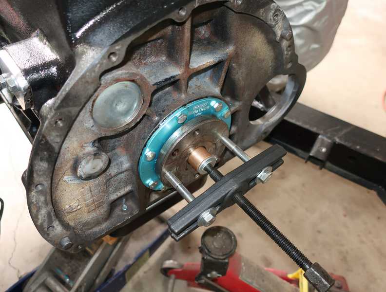
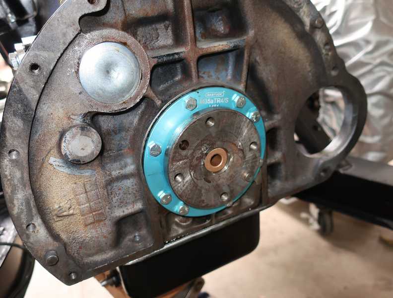
The blue flange is part of my aftermarket rear main seal. Unlike the standard scroll "seal," it does a good job of eliminating oil leakage from the rear of the engine.
The flywheel went on next. This is the later design, which does not use locking plates. Instead, it uses a "locking bolt," which, as far as I can see, does no more locking than any other bolt. The only difference is in its head, which takes a 5/8-inch socket; 9/16 is standard for 3/8-inch bolts. I installed the four bolts with Loctite and torqued them to 55 lb. ft., a little over the manual spec of 46, to compensate for the rapidly-hardening thread locker. A little higher torque is probably warranted, as the bolts are British grade X, which is stronger than SAE grade 8. The manual spec is for the bolts that use locking plates; there is nothing in the TR4A addendum for the newer bolts. Of course, I used new bolts.
The flywheel bolts are 7/8-inch long. That is just a smidge too long for the new rear seal; the bolt ends have a reputation for damaging it. I measured the amount of space, and it was just a hair under 7/8 of an inch. The bolts had to be ground down a little; removing one to two threads (about 40-80 mils) was enough. When I grind a hardened bolt, I'm always careful to avoid heating it very much. In theory, heating can destroy its strength; I don't know if that's a real danger, but I try to stay safe.
Using thread locker correctly requires some care. I first chased the threads with a tap, then sprayed them with carburetor cleaner to clean out any oil and remaining dirt. (The crank flange had only through holes, which dried out quickly; with blind-tapped holes, it's best to blow them out with compressed air, to dry the threads, after cleaning them.) I then sprayed Loctite primer into the hole and onto the bolt threads, and put Loctite (nonpermanent, of course) thread locker on both the bolts and inside threads. Once this was done, it was necessary to get the bolts torqued quickly; when primer is used, the thread locker starts to set up almost immediately.
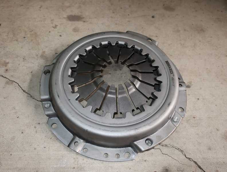
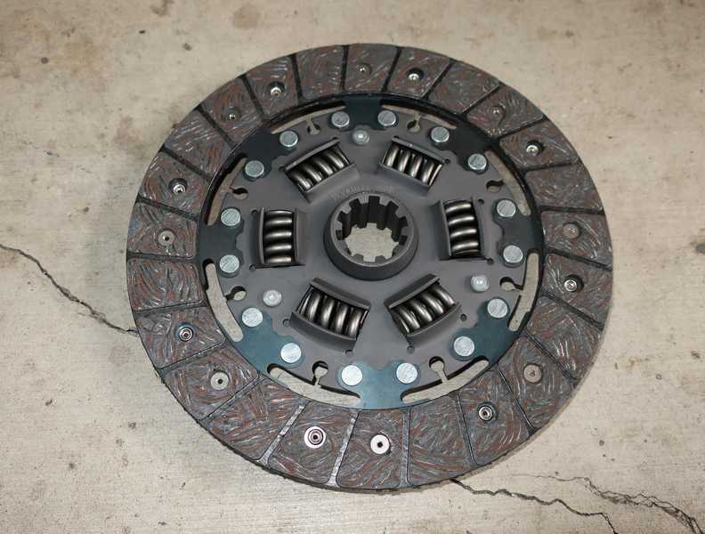
Here's my pretty new Borg and Beck clutch.
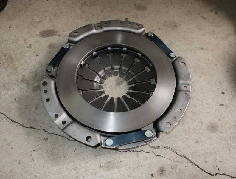
The disk is marked, near the center, to show which side goes toward the flywheel. That's convenient.
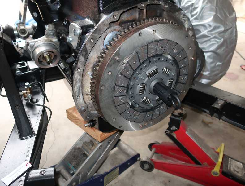
First step in installing the clutch was to clean and chase the mounting-hole threads, as described above, in preparation for using thread locker on them. Then, the flywheel surface was cleaned and the disk was installed with the centering tool.
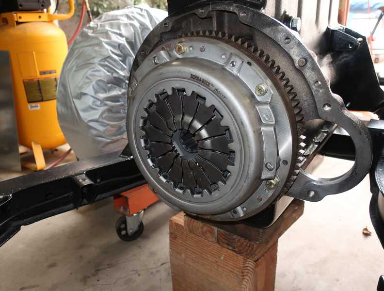
Finally, the pressure plate was installed and the bolts were torqued. The spec is 20 lb. ft., which might not seem terribly tight, but it is a fairly high torque for a 5/16-inch bolt. I used grade 8 bolts and lockwashers; grade 5 probably would have been fine, too, but anything lower would have been marginal.
The pressure plate uses six bolts. The bolts can't be installed sequentially, as the thread locker sets up too fast to allow proper tightening. It's better to install all the bolts dry, then remove one at a time, apply the locker, reinstall and torque it.
The release bearing, actuator, and so on were assembled in the transmission bell housing. They are described in the Transmission page.
The slave cylinder was restored and, once the transmission was mated to the engine, installed and adjusted.
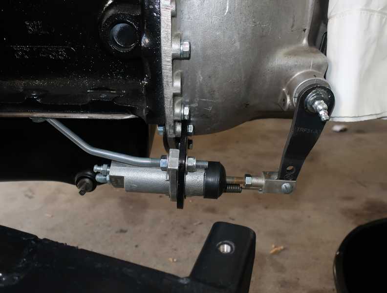
Restoration of the slave cylinder, along with the brake and clutch master cylinders, is described in the Brakes page.
Transmission and Overdrive
The transmission was in decent shape. I took it apart for inspection, internal cleaning, and replacement of a very few worn parts. It didn't need much work. I did replace all the synchros, however, even though only one really needed replacement, expecting that to be a relatively cheap way to maximize the transmission's life. The description of the transmission and overdrive restoration started to get a little long, so I created a separate page for it: Transmission and Overdrive.
The synchros are the main thing that need attention in a transmission rebuild. The synchros for this box are not expensive; the high-end ones, which I used, cost only about $100 per set. There are also some brass bushings that often must be replaced, and, occasionally, bearings. Of course, seals should always be replaced. Fortunately, it's unusual for the gears themselves to need replacement. Although they have non-replaceable friction surfaces for the synchros, the gears are designed to let the brass synchro rings wear preferentially. The shaft for the laygear is a weak point in this box, as it wears quickly, especially near the first-gear end. Uprated replacements are available, though, and after finding wear on the existing shaft, I installed one.
Common leak points on this transmission are (1) the brass plug under the overdrive pump, and (2) the adapter plate between the overdrive and transmission. The gaskets provided in the gasket kit are wholly inadequate to seal these points. I wasn't able to seal those perfectly. If I ever do this again, I will make my own gaskets from a soft, 0.060" gasket stock, and I'll use plenty of sealer.
The overdrive has relatively few components that wear out, mostly things like seals, bearings, and o-rings. It is possible also that the ring clutch might need replacement; that's an expensive and difficult job. Properly lubricated, the original Timken ball bearings seem to last forever, but rubber o-rings and seals harden with time, temperature, and oil exposure. As I took it apart, it became clear that the overdrive needed little more than cleaning, rechecking of adjustments, and seal and o-ring replacement. I did replace the actuator solenoid, as the old one, while still working, had experienced a long and difficult life, and I was concerned about its reliability.
![]()
![]()
![]()
The rebuilt transmission sat on the shelf for several months until I was ready to install it.
Drive Shaft
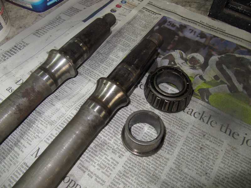
The drive shaft needed cleanup, painting, and new universal joints. Although the universal joints seemed to move smoothly, they were quite old and showed their age. The best option was simply to replace them.
The first task was to remove the old universal joints and degrease the drive shaft. It was a slow, dirty, and frustrating job, as the snap rings were stuck in place by crud and the bearing cups were tight. But finally the shaft was apart.
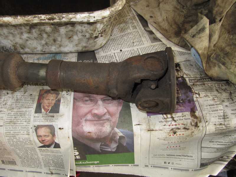
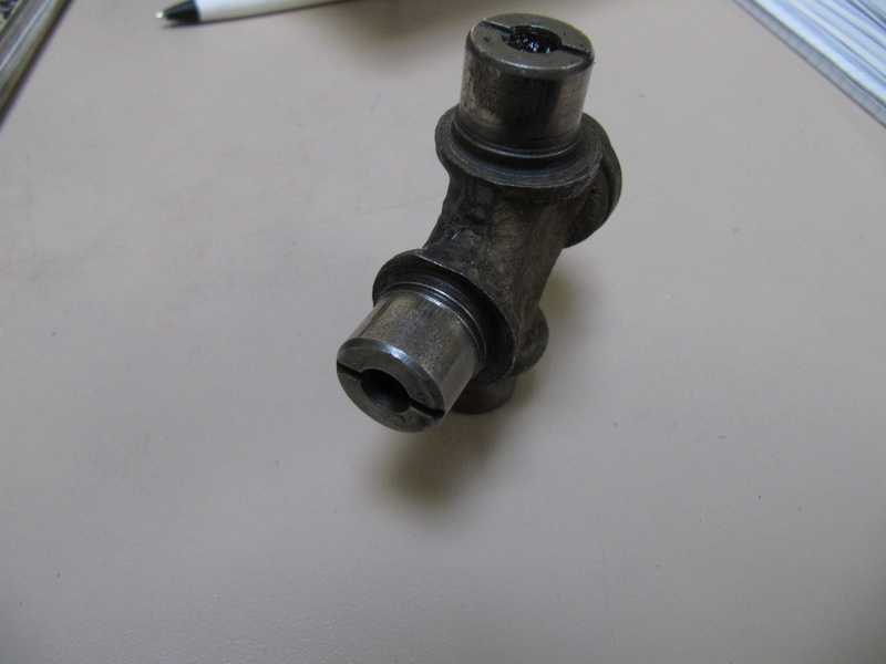
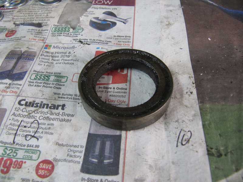
In the picture below, you can see some corrosion on one of the universal joint's bearing surfaces. All four surfaces of both joints showed similar corrosion; it's normal, high-mileage wear. Although a joint like this could still be used, it has one foot in the grave and is best replaced.
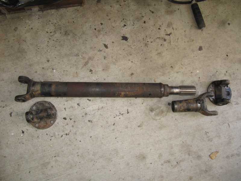
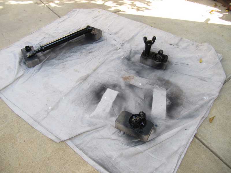
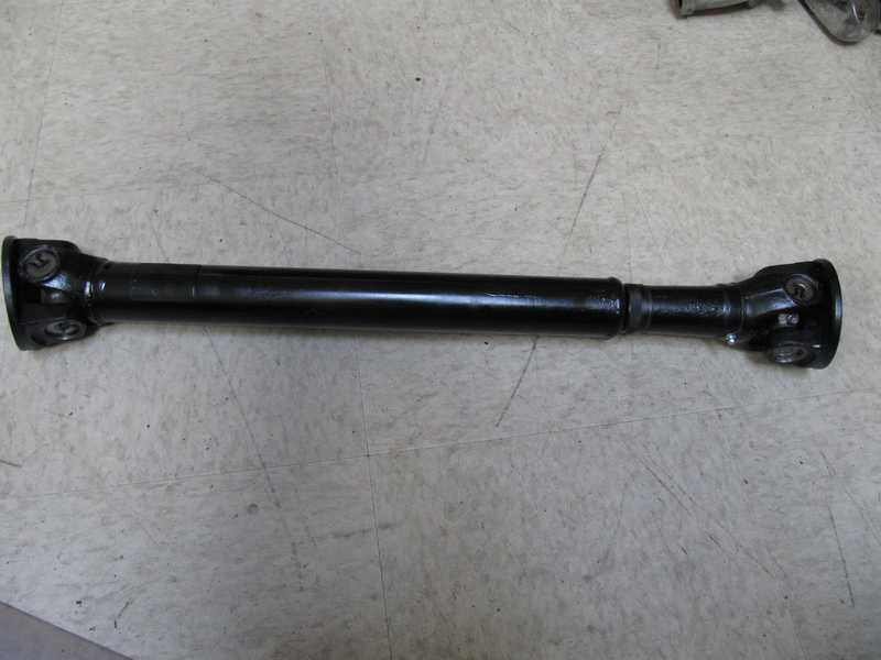
The drive shaft pieces were cleaned in solvent and wire-brushed to remove old paint and dirt. They were then primed and painted. As the cork seal for the spline joint seems difficult to find, I made a new seal from 3/16" cork sheet. Before assembling the joints, I filled them and their cups with grease. Finally, it was all back together.
Rear Axles
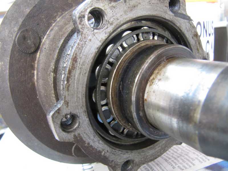
Once the rear brakes were removed, I could get a sense of the condition of the axles. I immediately noticed about 20 mils of end float, instead of the specified 4-6 mils. That was a sign that I might need to replace bearings; no great surprise. After cleaning the axle housing, I started to disassemble it and see what I had.
The inner oil seal on the right side was totally wasted, and the left one was bad, too. There was no visible grease at all on either of the bearing; it might have been washed out by oil leakage. The differential had only a few ounces of oil in it, and the axles were dry and had some light rust.
I've observed that owners rarely check, let alone change, the rear-axle oil, even though both operations are clearly indicated in the maintenance schedule.
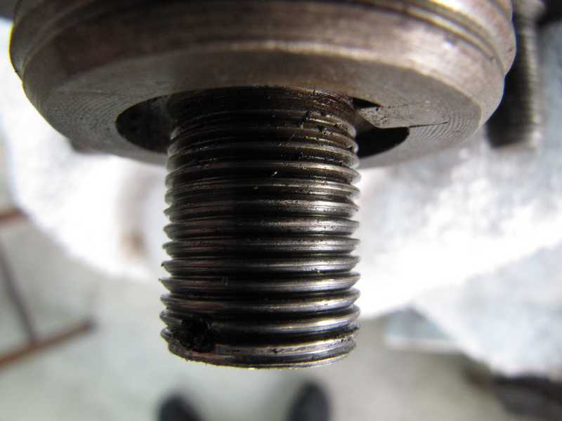
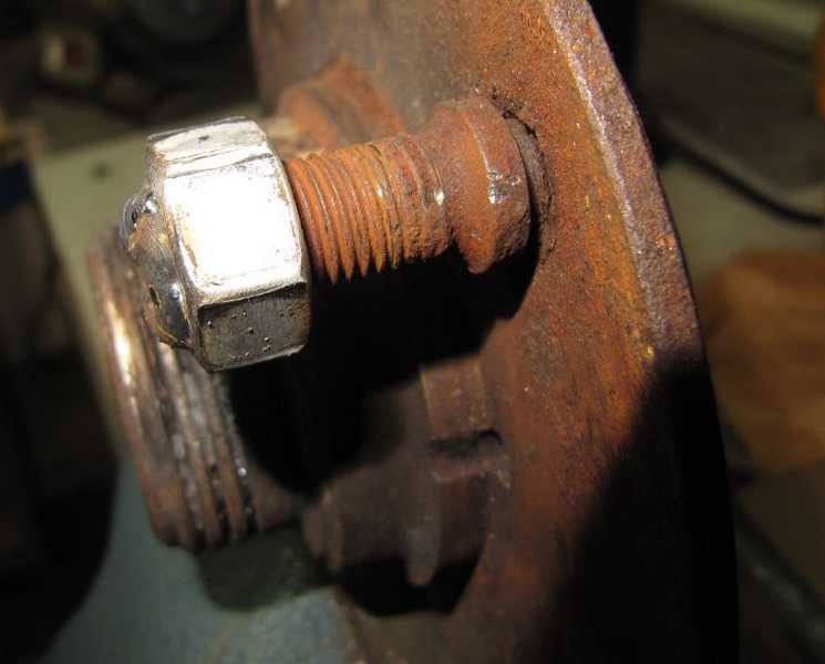
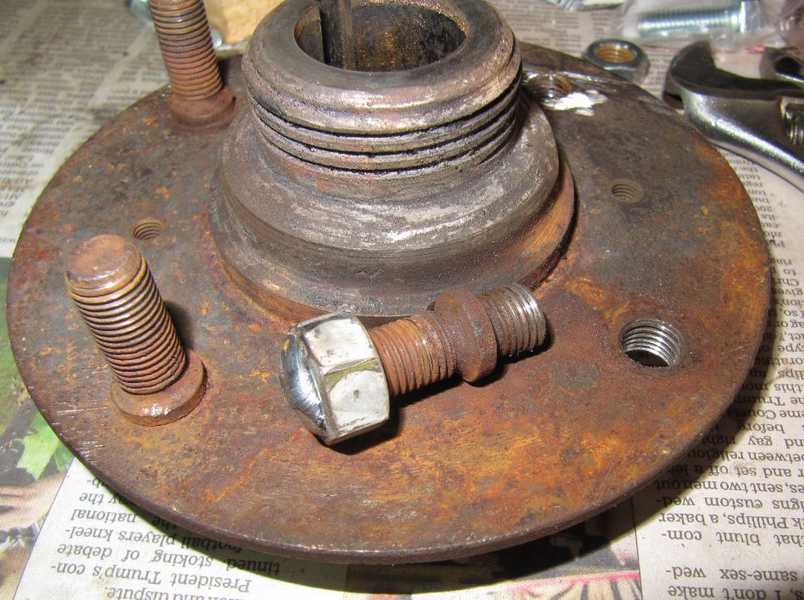
The nut on the right axle was difficult to remove, and even when loosened, it did not thread freely onto the axle. A close-up shows why: the thread profile is flat on one side. The threads were probably bent by someone trying to press the axle out of the hub while putting the force on the nut instead of the axle itself.
I found also that the hub flange on this axle had 0.010" runout. I could find no spec for this, but ten mils seemed way too much. The high points were at two lugs on opposite sides. I suspected that someone tried to use a hub puller to separate the hub and axle; that never works, and it often warps the hub. So, to take stock: the flange was warped, the threads were boogered, and the bearing was shot. I decided that this axle and hub needed to be replaced.
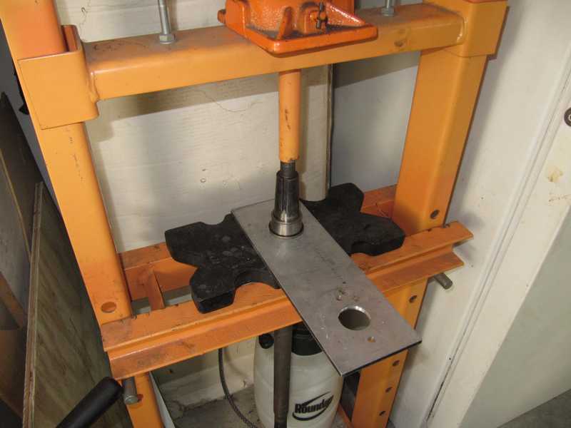
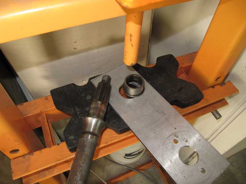
I bought a pair of used axles and hubs on eBay. They came with brake drums, backing plates, and a pile of other hardware, which I didn't need but someday may find useful. Fortunately, the hubs were separated from the axles, but I had to remove the remains of the hub bearings. They were remarkably tight. I removed them by making a 1 3/4-inch hole in an aluminum plate, backed it up with the steel plates on my press, and pressed them out. With this setup, the bearings came off fairly easily.
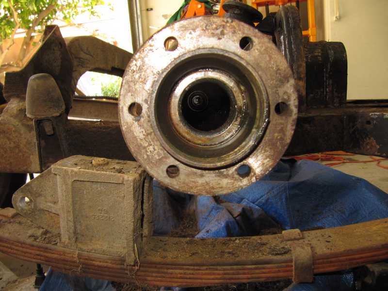
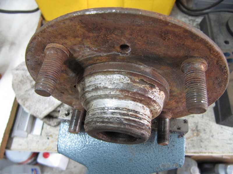
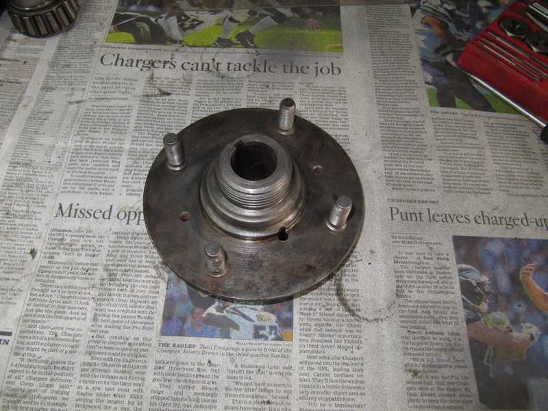
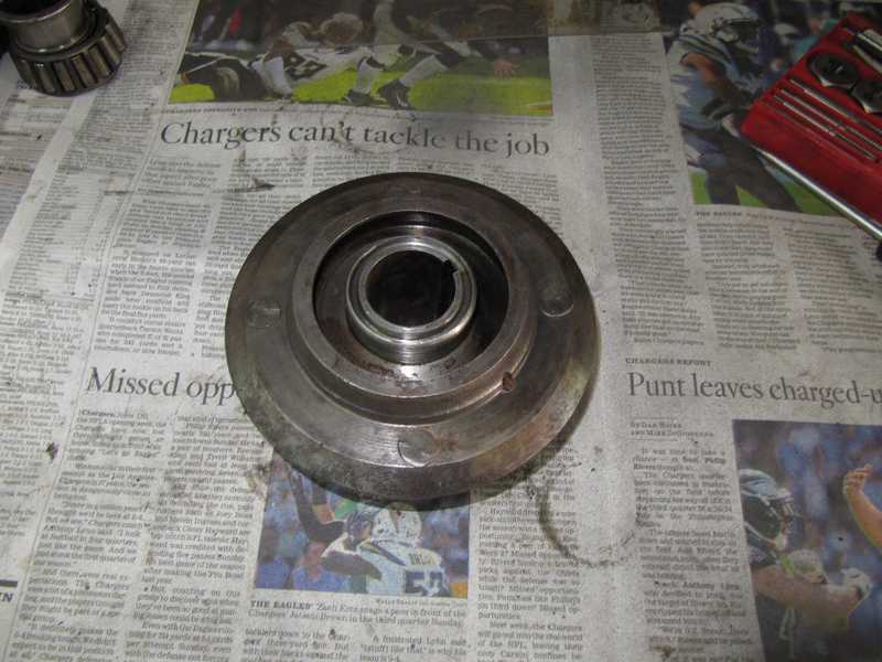
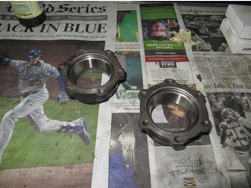
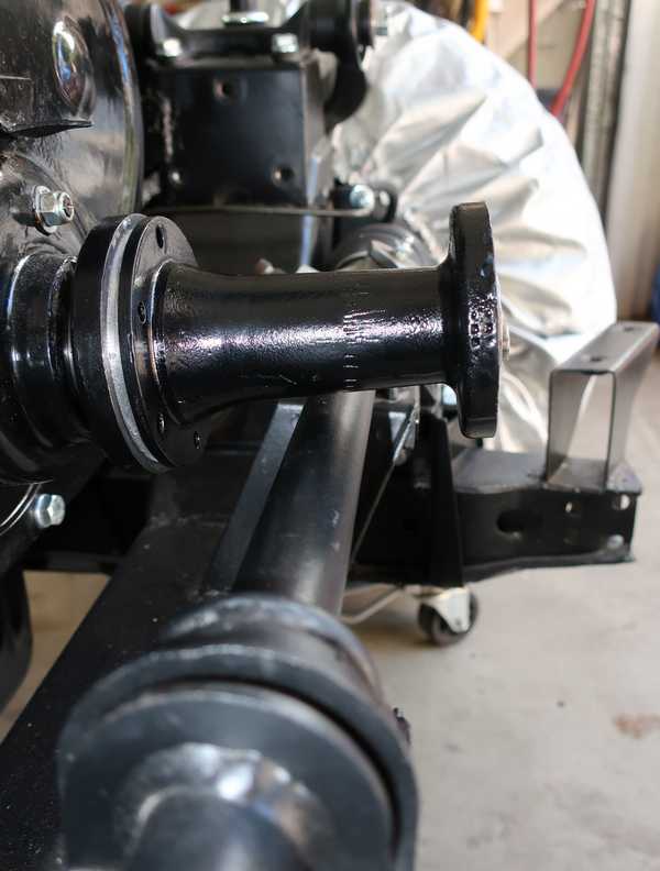
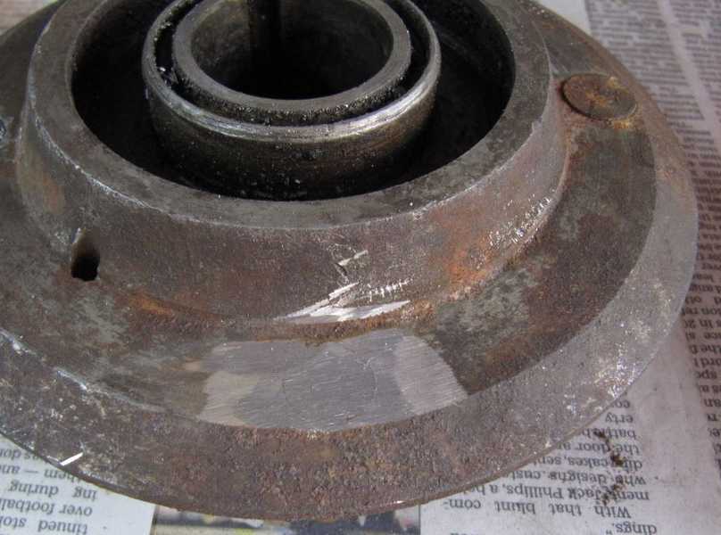
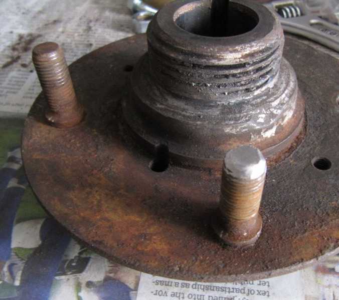
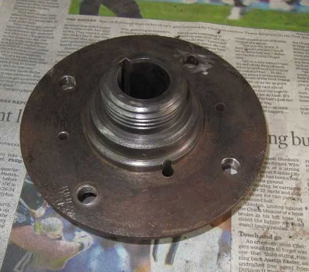
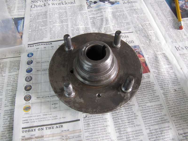
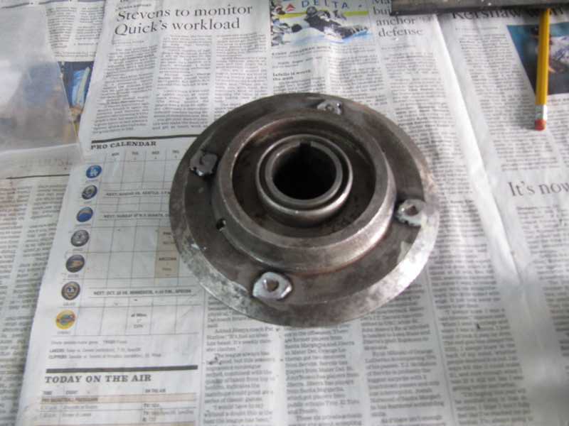
The hubs were decent. One needed the wheel studs replaced (see below), but the other required only chasing with a die and clean-up. The latter hub is shown below. The first picture shows the hub as I received it; in the second two, it has been cleaned.
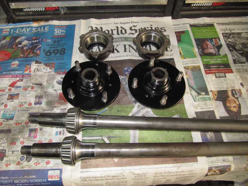
I cleaned the replacement hubs and axles, then painted the hubs. I replaced the bearings on both sides. Pressing the bearing cones onto the axles and races into the bearing housings, which I had painted earlier, was straightforward.

Here they are, ready for assembly.
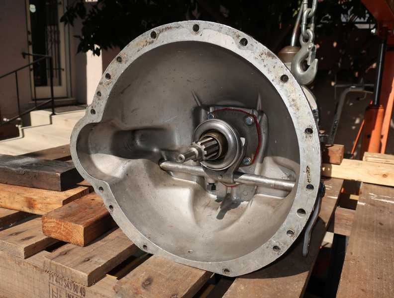
Rear Axle Case and Differential
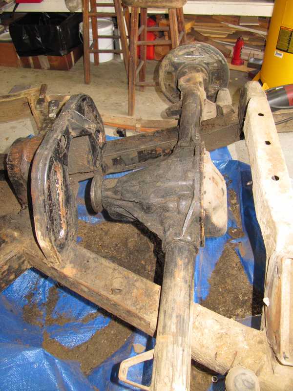
The rear axle was covered in a quarter-inch of oily dirt. Before I could do anything else, I had to give it a good cleaning.
Cleaning the rear axle case, as with other components, involved scraping off the heavy crud and then washing it with solvent. In the first picture below, it has been scraped; second, degreasing; third, drying in the sun.
After it was degreased, I washed it with a strong detergent and rinsed it. Once it was dry, I went over it with the rotary wire brush and then primed it.
At this point, I still needed to check it internally; I delayed those checks until it was primed, as I didn't want to work on a cruddy unit. I put off final painting until I was done working on the interior. As it happened, the differential was a horror story and needed a complete overhaul; that is described here.
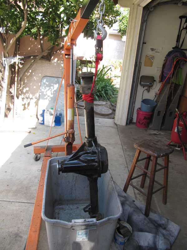
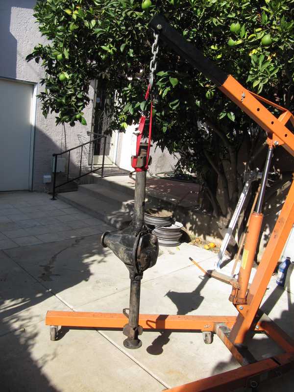
Once the differential overhaul was finished, I could turn my attention to other things. First, I tried to remove the axle oil seals but broke my seal remover in the process. I welded it back together. Now it's stronger than ever, but it still won't remove those deeply embedded seals.
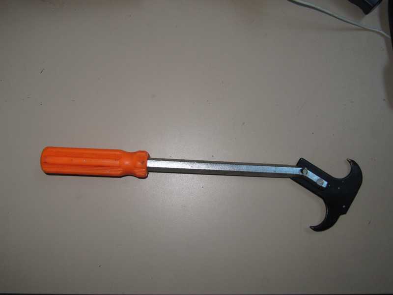
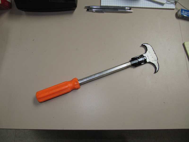
I made a special tool to remove the seals, a simple puller consisting of two pieces of 1/2-inch square steel tubing and a long 5/16-inch bolt. The axle seals, like the pinion seal, were leather; they may well have been original.
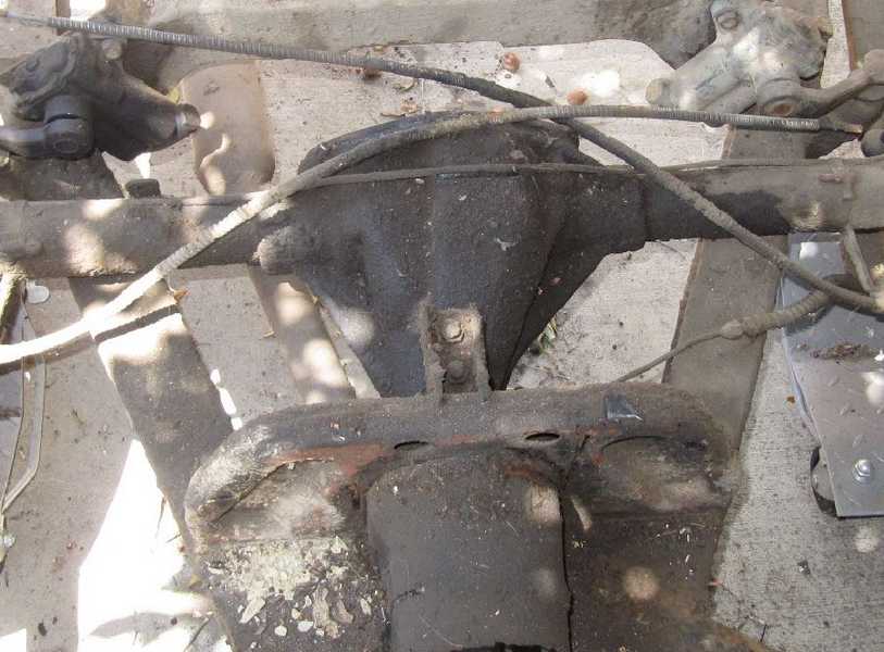
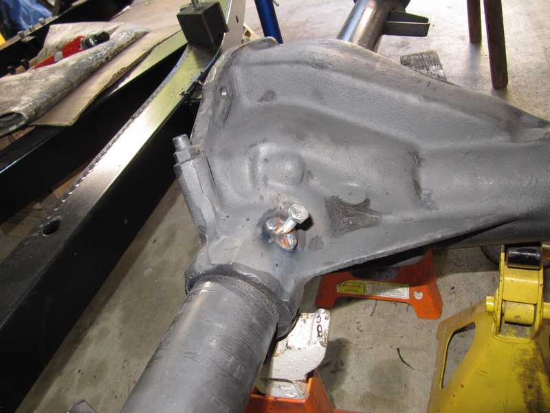
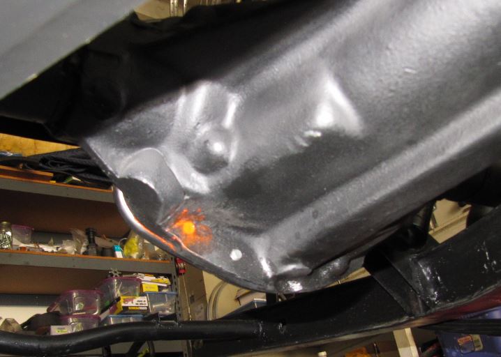
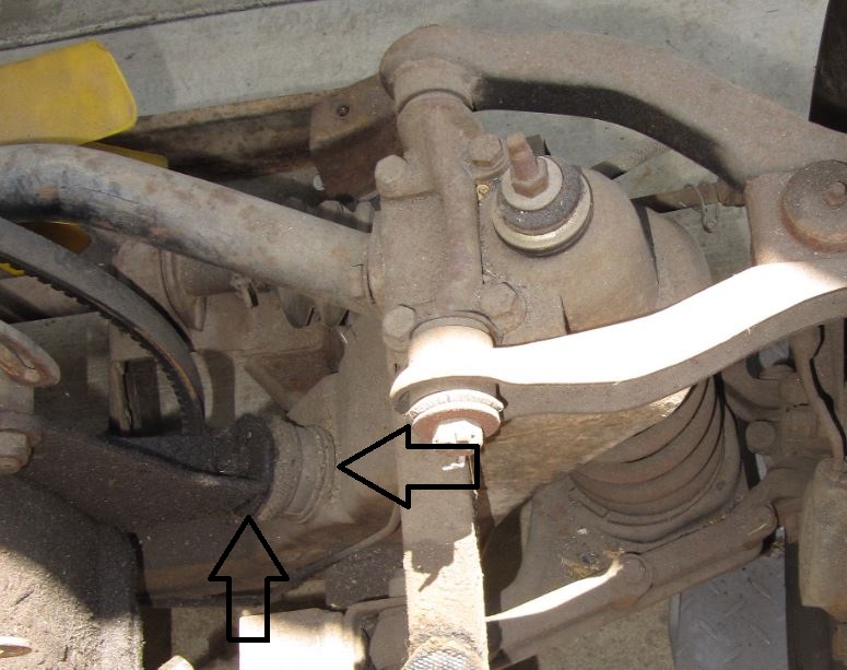
I discovered that the right-side axle tube was loose, allowing perhaps 50 mils of movement at the outer end. Each tube is held in place by four pins that are staked to prevent them from moving, but that clearly doesn't work very well. You can see one in the picture below.
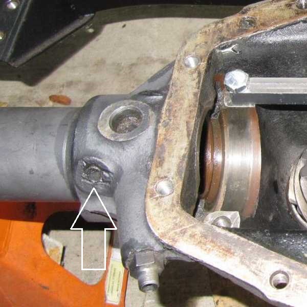
Three of the four pins on the right side were loose. At first, I suspected that the pins were 3/8-inch screws that had been tightened and cut off, then staked to prevent loosening. It became clear, however, that they were not screws, as they rotated easily in their holes without coming out. I hoped that I could remove them, tap the holes, and replace them with screws. The pins, while loose in their holes, were still not easy to remove. Then, there would have been the additional problem of realigning the axle.
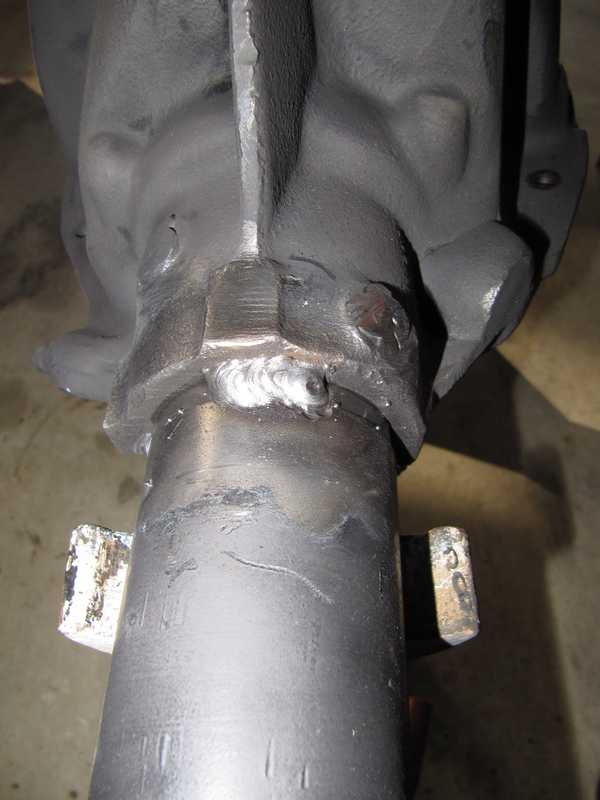
Instead, I clamped each loose pin so that it fit into its existing depression in the axle tube, then welded it. I placed a 1/4-inch bolt between the clamp and the pin, so I could weld the pin while it was held tight. I cut off the bolt, which inevitably got welded to the pin, and ground the weld a bit thinner, still leaving adequate metal thickness. That left the tube nice and tight.
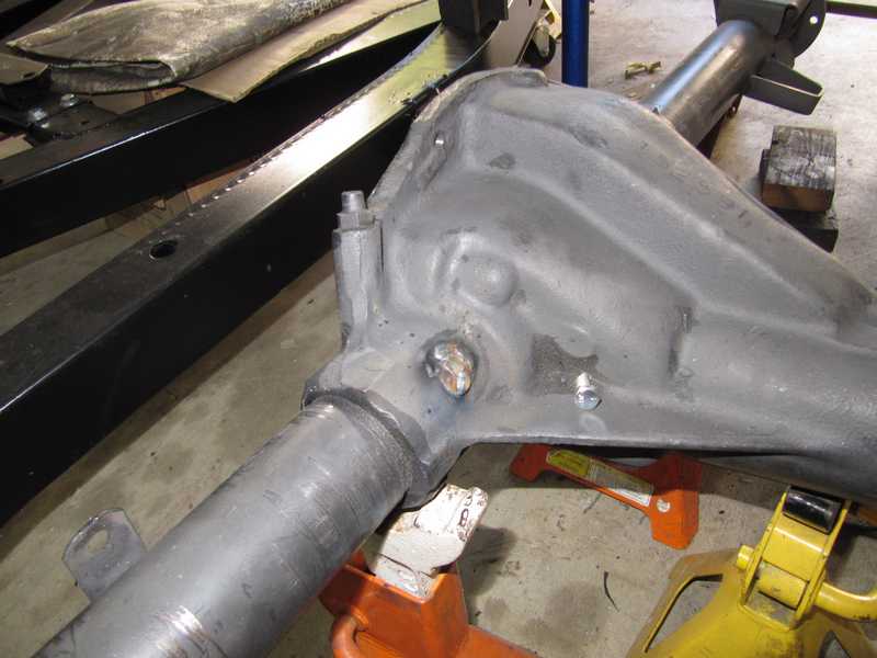
I did all four pins on the right side, then tack-welded the ones on the left, to make sure they didn't loosen like the others. Additionally, for a little insurance, I made three one-inch welds evenly spaced around each joint.
This experience provides one good reason why a car should not be raised by a jack located under the differential, even though the shop manual suggests it.
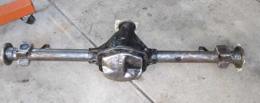
I reprimed the welded areas, then painted the entire assembly with the same Rustoleum semigloss that I used for the frame. In the first picture below, it is primed everywhere except the welded areas (which were reprimed after welding, of course); in the second, it has been painted and is drying.
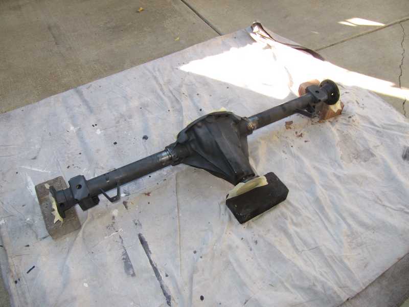
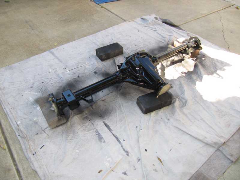
I gave the paint a day to dry, then installed the rear axle onto the frame. Without axles and other pieces, it wasn't too heavy to lift, so I just picked the big motha up and set it where it belonged. Towels on the frame protected the paint.
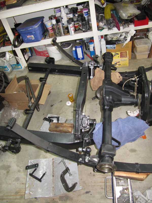
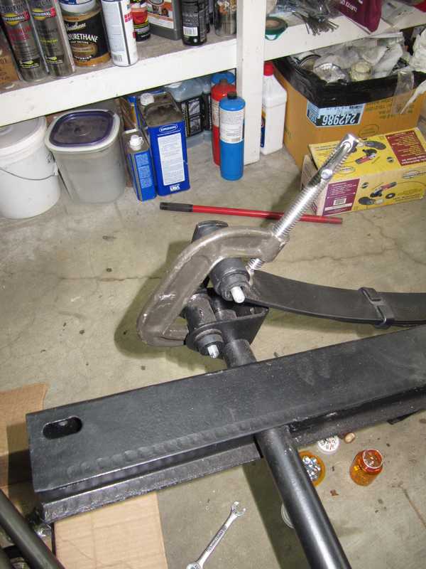
There still wasn't enough weight on the springs to bend them into position, so I had to disconnect the rear shackles. Once the rear axle was mounted, I could bend the springs enough to reinstall the shackles, but it took all my weight. I used a large C clamp to take the stress off each shackle so I could slide it into position.
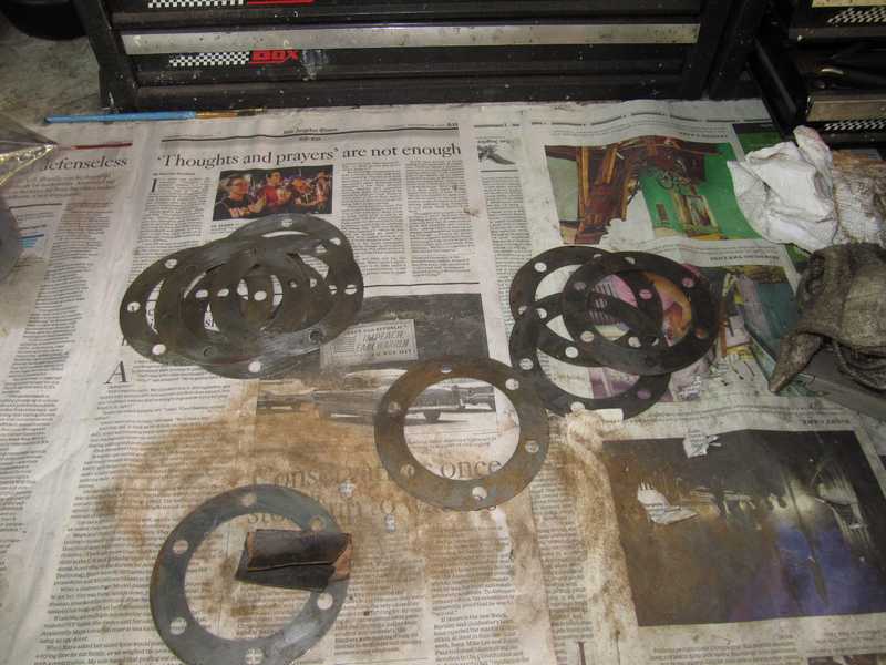
The original setup had quite a few spacers, and the axles I bought to replace the original ones came with some as well. Many were a little rusty, so I sanded them clean. I had more than enough spacers.
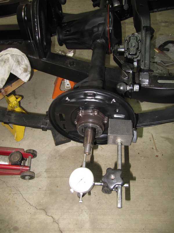
The end float is easiest to measure and adjust if it is done before the axle-tube seals and hubs are installed. I started with two 31-mil spacers, which gave 3 mils of end float. Second try, I replaced one 31-mil spacer with a 33-mil stack, which gave 5 mils, right in the center of the 4-6 mil spec. Ideally, we should have equal stack thicknesses on both sides, but the available spacer sizes often do not allow that. The 2-mil difference is probably unusually good. Once the end float was correct, I installed the axle-tube seals, greased the bearings, and permanently installed the axles.
Because accessibility was better, I installed the brakes before the hub and nut.
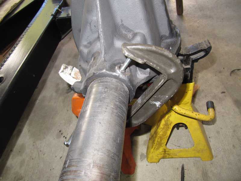
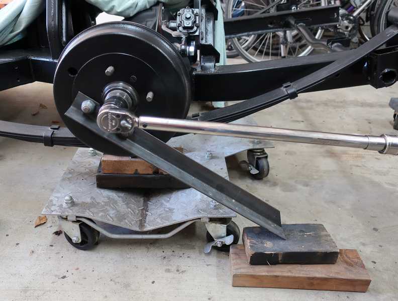
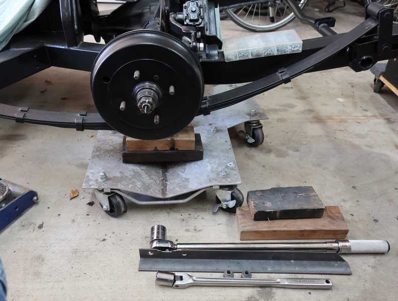
The hub nut must be torqued to 125-145 lb ft., and the hub must be locked in position while the nut is torqued. If you try to lock the hub simply by jamming something between the lug nuts, it's likely that they will be damaged. Instead, I made a simple locking tool from a piece of angle stock.
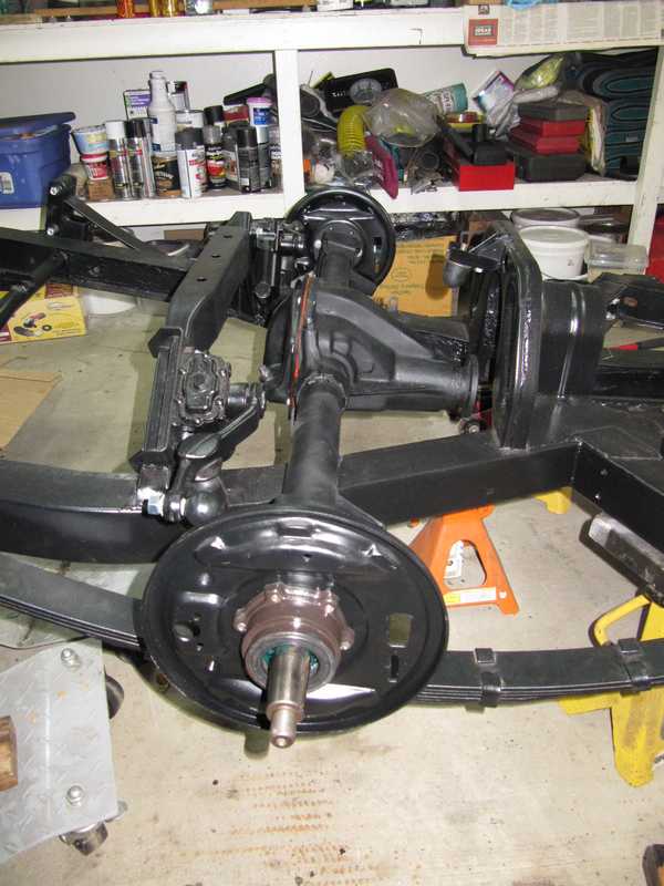
Below is the finished rear axle, installed in the car.
To check for leaks and to prevent rust formation on the internal parts, I added gear oil to the differential. I soon noticed a very small leak, only a couple drops per day but enough to make a mess. I traced it to one of the unthreaded holes in the housing flange. I cleaned the hole with carburetor cleaner and Q-tips, blew it dry, and packed it with the same Permatex sealer I used for the gasket. That ended the leak; hope it stays that way.
Engine and Transmission Reinstallation
Engine Installation
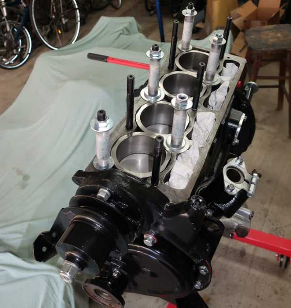
I removed the engine from the stand and wiggled it into place on the chassis. The front was supported on new engine mounts, but since the engine has no rear mounts, I used a piece of wood temporarily to support the rear. Note that I did not lift the engine by the head studs; that's an excellent way to bend the studs or to crack the block.
To make it easier to manipulate, I installed the engine without the cylinder head. It would have been awkward to install the cylinder head with the engine on the stand; much easier to do it once the engine was in the chassis.
Transmission and Drive Shaft
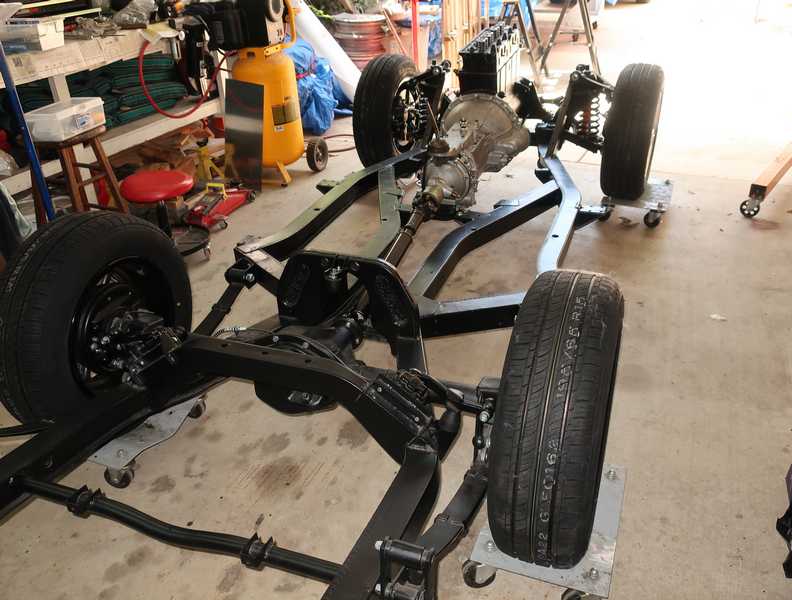
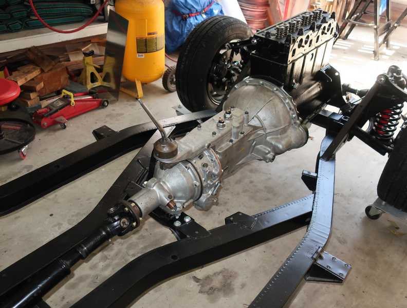
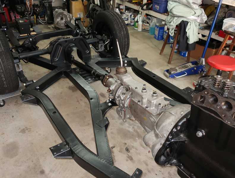
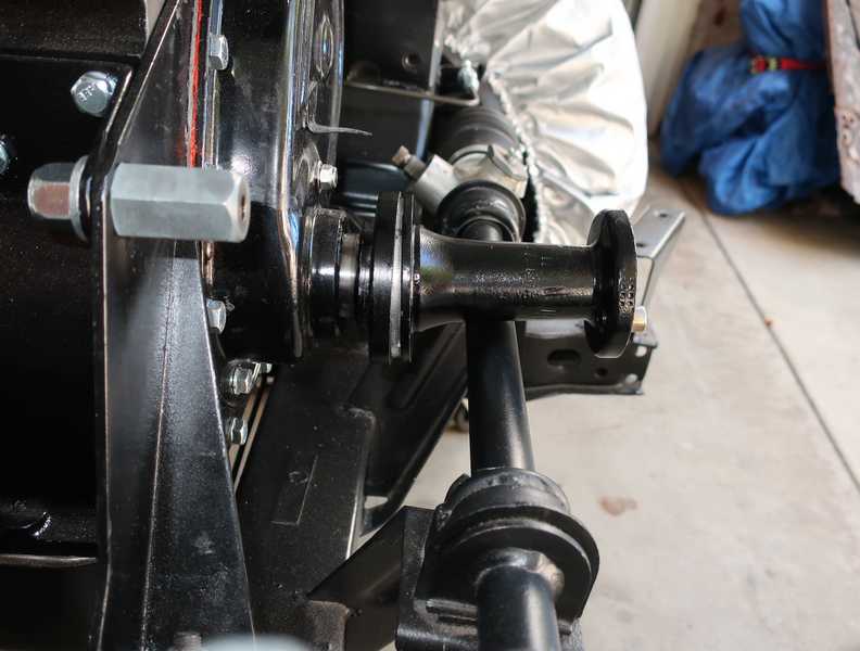
Once I got the crane into a workable position, the reinstallation of the transmission went smoothly. I used long, 5/16-inch bolts to align the transmission with the engine, leveled the whole thing with the crane, wiggled the output flange to line up the input-shaft splines, and simply pushed it home. Easier than I had expected. It was helpful to raise the rear of the engine a little on blocks, so the overdrive could clear the transmission mount.
![]()
![]()
With the transmission in place, I installed the drive shaft. I used the special bolts with a long, unthreaded shank but, frankly, I doubt that it matters a lot. The drivetrain installation was then finished. There still was plenty to do, of course, but at that point, it was really starting to look like a car.
Main Pulley and Fan Pedestal
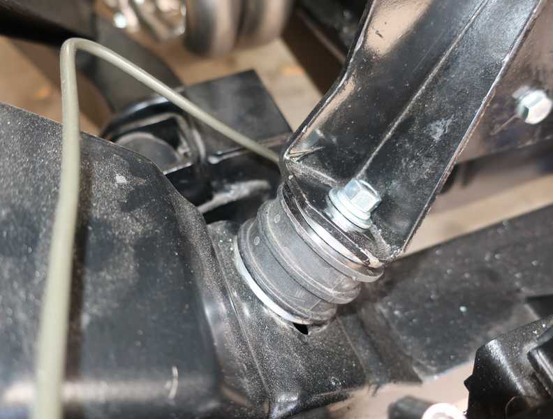
The fan pedestal didn't fit. It interfered with the steering rack. Apparently, the engine was sitting about a half inch too low.
The shop manual does not show any spacers between the chassis and the engine mounts. The mounts on the car when I received it, however, did have two spacers, each perhaps 0.1 to 0.2 inches thick. (After all my bloviating about saving old parts, I couldn't find them; I might have discarded them.) It also seems likely that modern replacement mounts are not the right thickness. Wouldn't be the first time that new parts didn't fit.
I fabricated four aluminum spacers, approximately 0.2 inches thick, and placed one on each side of each mount. The extra 0.4 inches allowed the pedestal to clear the steering rack with enough space to allow installation of the fan belt.
I have since learned that this is a common problem, especially when today's ordinary replacement mounts are used. I'm told that there is a Land Rover mount which fits and is much better quality, but expensive.
![]()
I trial-fit everything, and it looked good. I discovered, however, that the bolts for the main pulley must have their heads toward the inside; if they are on the outside, the bolt ends and nuts interfere with the timing cover.
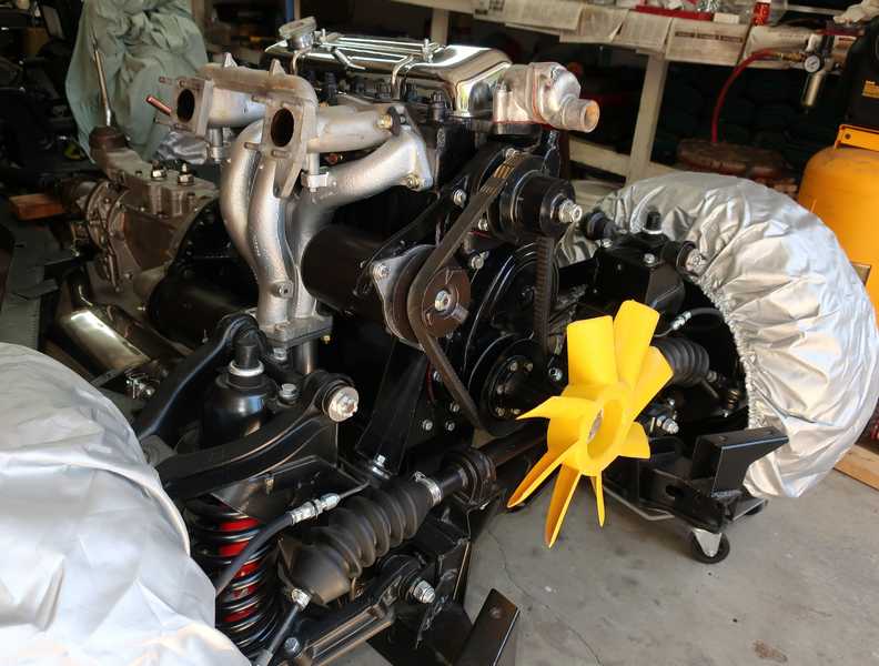
Much later, a potential disaster was averted when a friend noticed that the fan was loose. I had not adequately torqued the long 5/8" bolt that holds on the fan, pedestal and, as it happens, the crankshaft timing gear; it had loosened when I test-ran the engine. With this fan, from a TR6, the bolt cannot be torqued enough, as it might crack the plastic body of the fan. To solve the problem, I made an aluminum bushing, a few mils smaller than the thickness of the fan body, so I could torque the bolt against the bushing and it still would hold the fan tightly in place.
Engine Start Up
I decided to test-run the engine before I got too far. That required installing almost the entire fuel, ignition, and cooling systems. The carburetors had to be removed before the body was installed, but the other components were installed permanently. That undersized radiator was a problem; when coolant was added through the radiator, in the usual manner, it was difficult to be sure that the coolant got into the head. To fill the engine completely, I disconnected the bypass hose and filled the head through the thermostat housing. That was a stupid arrangement; clearly, it had to be fixed. I eventually replaced it with a modern, aluminum radiator.
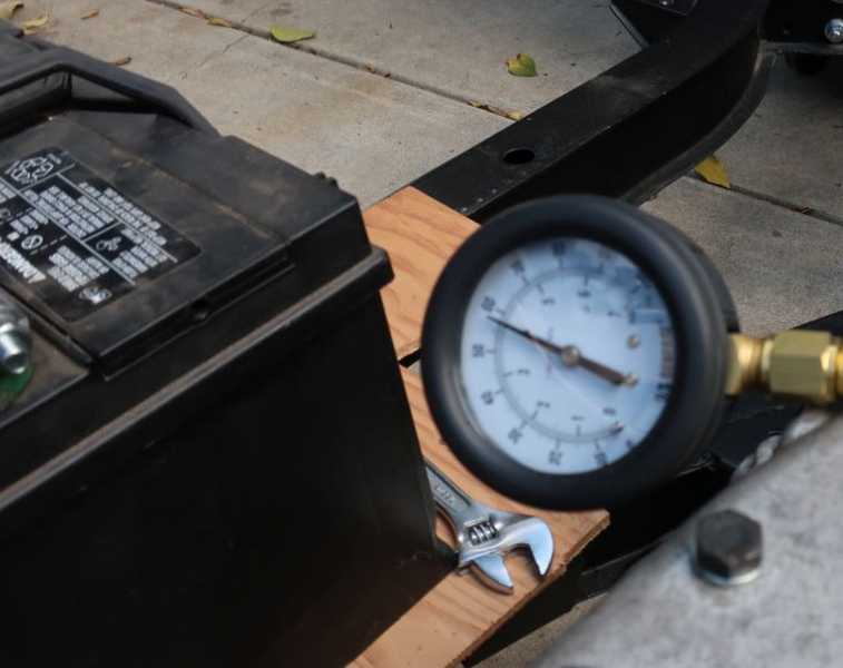
I installed the renovated distributor and static-timed it to 5 degrees BTDC. I also connected an oil-pressure test gauge.
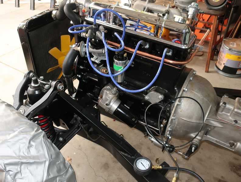
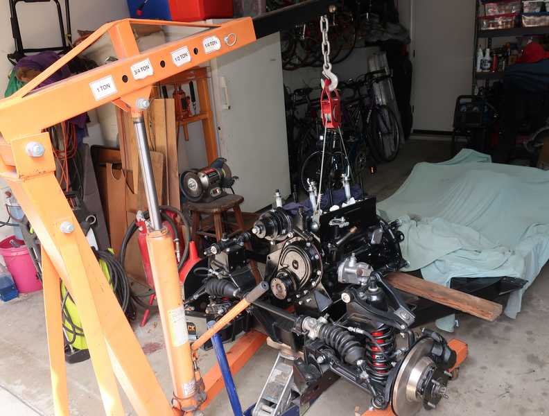
The first step in starting a rebuilt engine is to fill it with oil and crank it until pressure is obtained. It's best to do this with the spark plugs removed and the battery well charged, so it cranks fairly fast. The pictures below show my setup for this test.
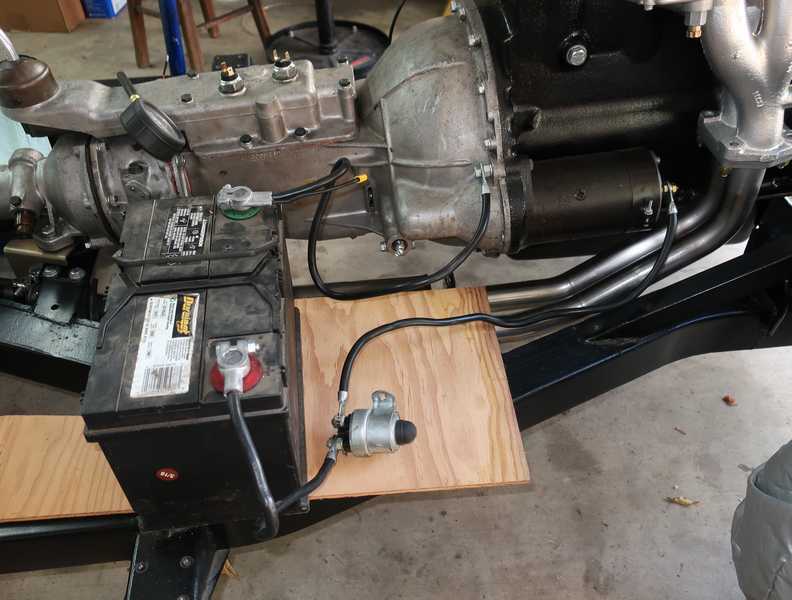
On some engines, this step--priming the oil pump--can be difficult. In the MG TD, for example, it's especially tricky, as the oil pump is mounted well above the oil level in the crankcase. To get started pumping oil, it first would have to suck some air, which it's not designed to do. Instead, it's necessary to prime the pump with oil, but in the earlier pumps, there is no easy way to do that. The only options are forcing oil backward through the oil system or packing the pump with grease. Fortunately, the TR pump is mounted fairly low, partially submerged in crankcase oil, so it self-primes easily. Filling the oil filter with oil before beginning also helps to speed the process. It took only about 20 seconds of cranking before the test gauge indicated pressure; I obtained 45 PSI at cranking speed, which seemed good to me.
For break-in, I used 10W-30 oil with a ZDDP additive. (After break-in, about 1000 miles, I changed it to 10W-40 with no extra ZDDP.)
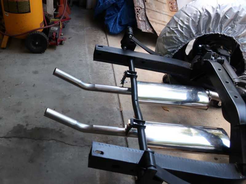
The start-up was the next task, usually a heart-in-the-throat effort. I moved the chassis out of the garage; if it caught fire (optimistic, yes?) I wanted it to be clear of all buildings. I kept a fire extinguisher and hose nearby.
For a fuel tank, I used an old one-quart acetone can with a quarter-inch fitting screwed into its bottom and sealed with JB Weld epoxy. The fuel line was a length of clear vinyl tubing; the clear tubing allowed me to see when the can was running dry. No pump, purely gravity feed.
I ran a wire from the battery to the ignition coil, cranked the starter, and the engine fired up instantly. It did not need much choke; I probably had preset the carbs fairly rich. I let the engine run for the requisite 20 minutes at 2000 RPM to bed in the piston rings. No sign of any problems.
The oil pressure was just a bit under 60 PSI, a thoroughly acceptable value, and I saw no oil leaks (except from the dipstick hole, since I forgot to insert the dipstick!) and no coolant leaks, except for the radiator, which I already had planned to replace. Not a wisp of smoke from the tailpipes; that's good news, too.
A successful test. On to the next stage!
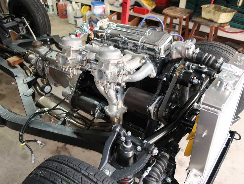
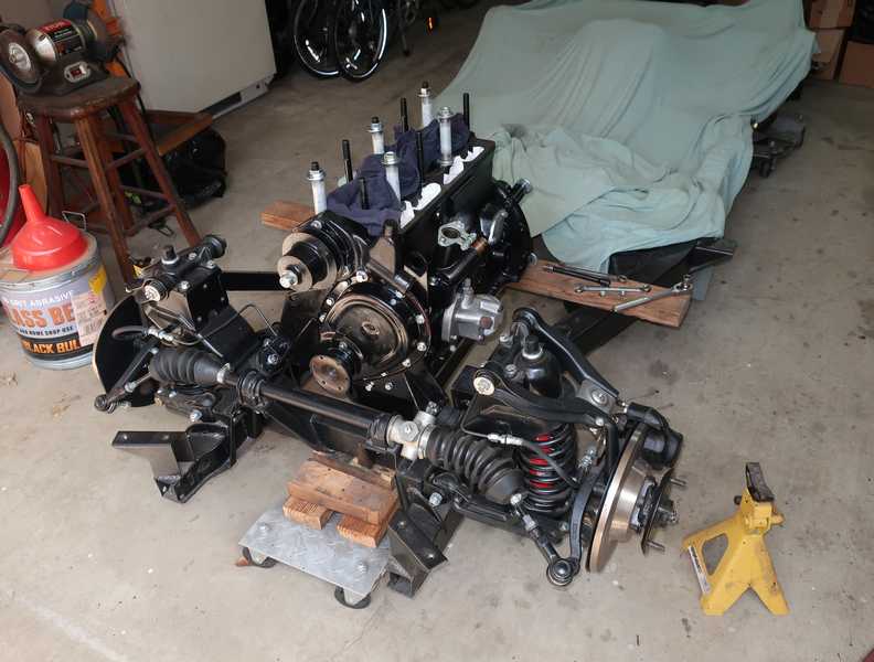
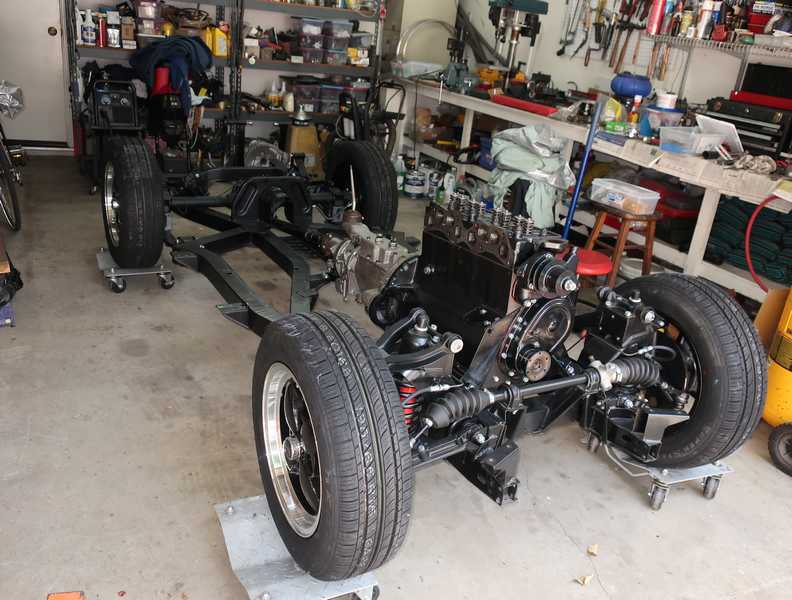
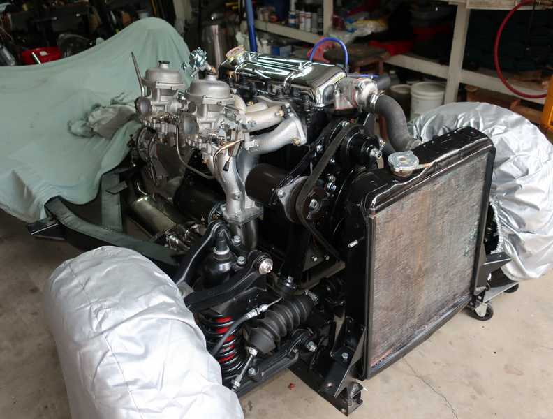
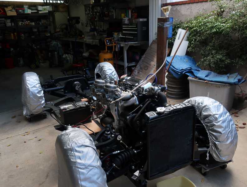
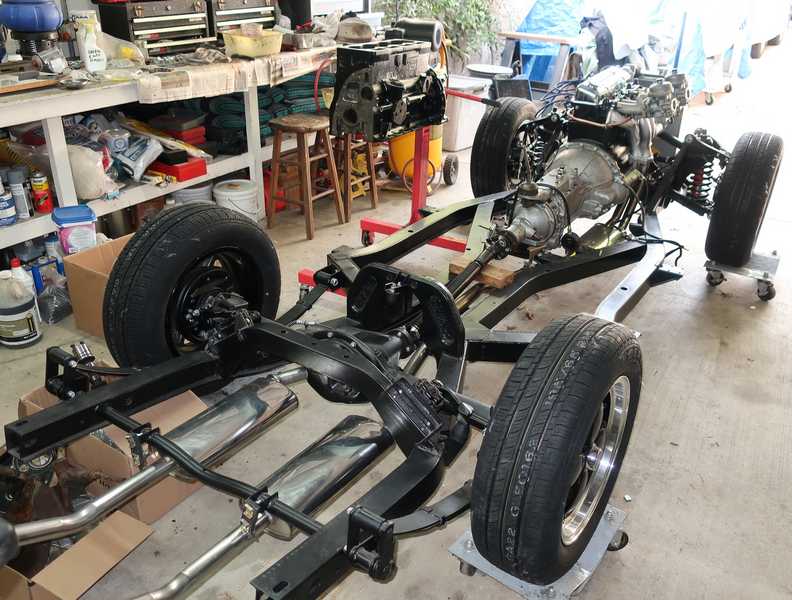
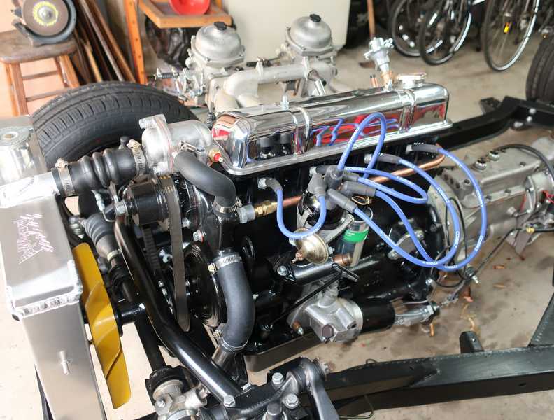
Completed Chassis and Drive Train
Well here it is, ready for the body to be installed. I've replaced the leaky, incorrect radiator with a new aluminum one and installed the last couple of frame pieces: the radiator shield and the crosspiece between the suspension towers.
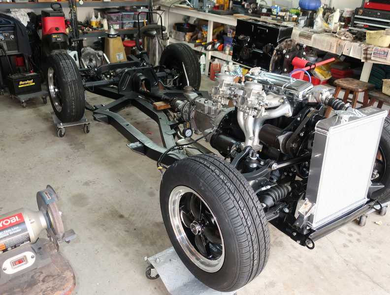
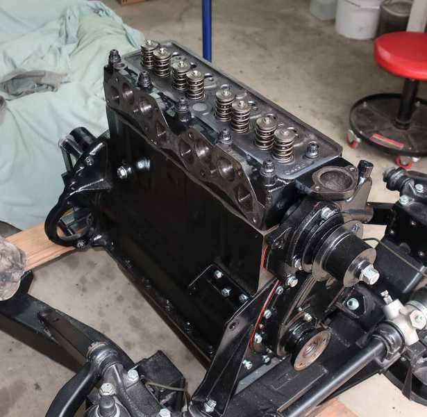
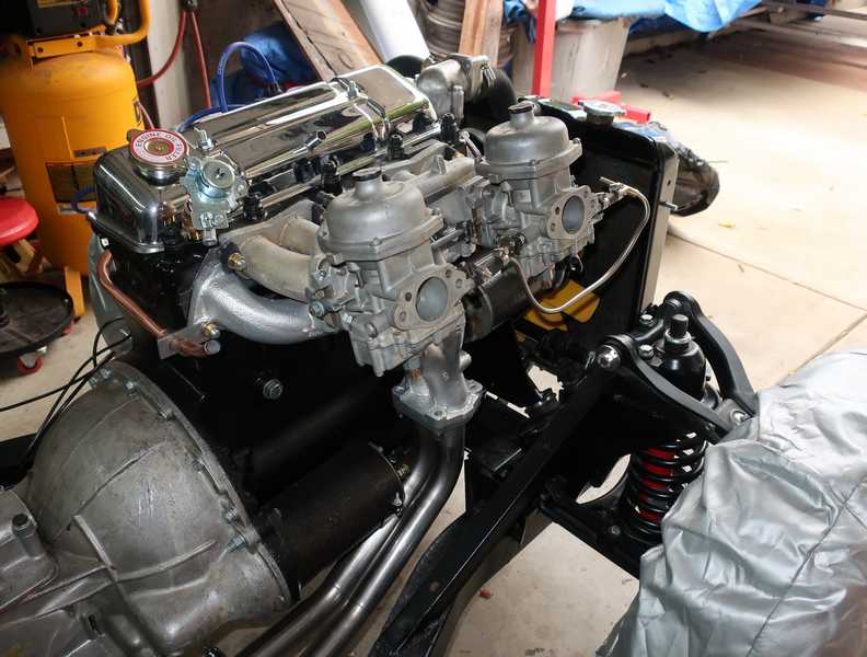
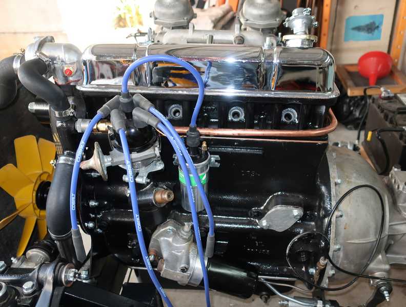
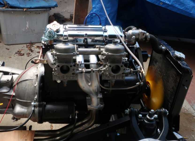
Here's the engine. The carbs will have to come off before the body can be installed, but for now I think I'll leave them in place.
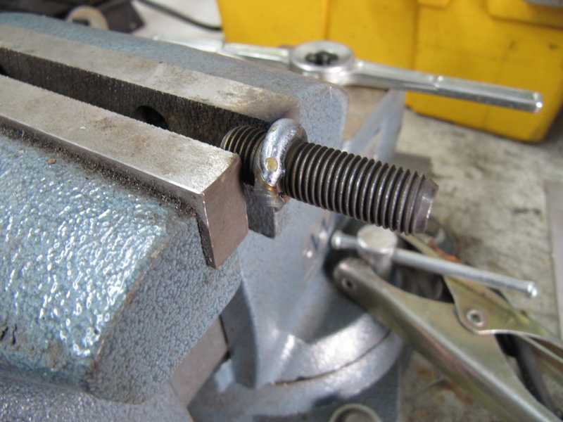
Rear Wheel Stud Replacement
By time a car is 50 years old, it's likely that the wheel studs need replacement. The threads on the studs of the hub shown below had lost quite a bit of metal from corrosion, and one was bent, so they all were replaced.
In most older cars, the studs are simply pressed into the hub flange from the rear. For the folks who designed the Triumph rear axle, that was far too sensible; instead, they were threaded in from the front, and the slight rear protrusion was flattened to make a head, of sorts. That makes removing them a little tricky.
To remove an old stud, I first carefully ground off its head, touching the flange as little as possible, so the stud was flush with the back of the flange. I also ground the stud's tip into a blunt point, then welded a nut onto the stud. Finally, I unscrewed the stud with an impact wrench. I discovered that it is possible to break a stud with the impact wrench. When that happened, I drilled out the remains of the stud and cleaned up the hole with a tap. It's possible to remove all the studs by drilling, of course, but that carries a significant risk of damaging the threaded hole.
By the way, that small flange on the stud is important, as it locates the brake drum on the hub. For that reason, the studs should be replaced by the original type, not by generic replacements, which don't have the flange. The back end of the stud probably should be welded, as most people don't have the equipment needed to squash it in the manner used at the factory.
I removed the other studs and cleaned up the hub with a wire wheel.
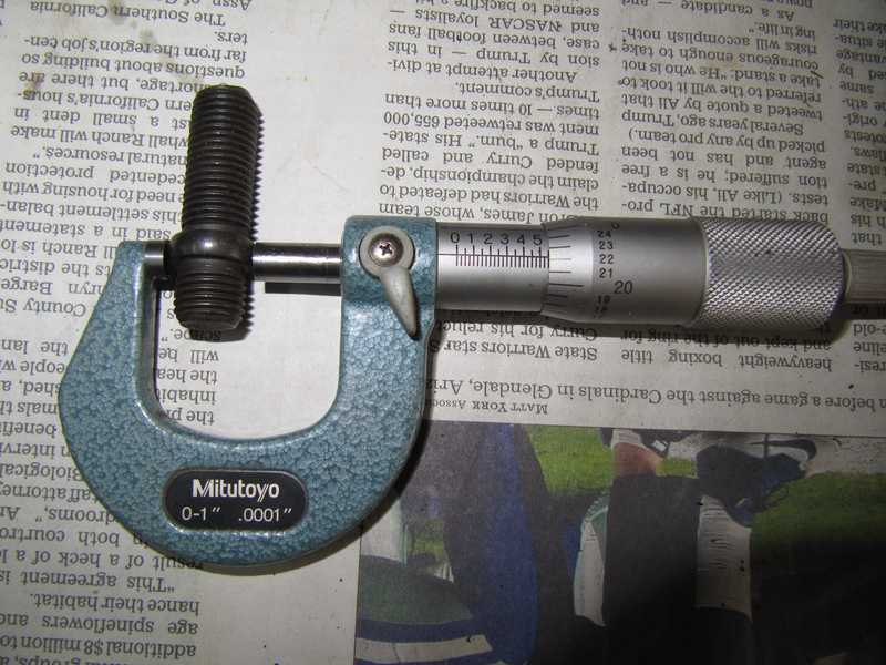
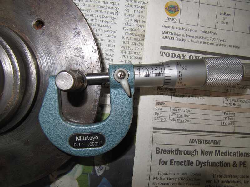
Here's why I always try to restore existing hardware instead of buying new parts. Apparently we can't even trust something as simple as a wheel stud to be made correctly. The flange on the new stud measured 0.547 inches; it should have been more like 0.570. That probably wouldn't matter much if I were replacing just one stud, but in replacing them all, it mattered a lot. With four new studs, there would have been more than 20 mils of slop in the mounting of the drum, allowing it to shift back and forth as the brakes were used. That could have worn the surfaces of the hub and drum, loosening the wheel. For sure, it would have quickly sheared off the 1/4-inch flathead screws that keep the drum in place when the wheel is removed.
After considering a number of options, I decided to weld some extra metal onto the studs' flanges and machine them to the correct dimensions. I then installed them in the hub, welded the reverse side, and ground the welds a bit, leaving some metal for strength.
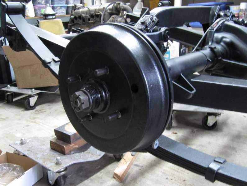
Finally, the hub was installed on the car. The brake drum fit perfectly.
Rear Hub Remover
Although I had a set of usable hubs and axles, I still wanted to remove the hubs from the originals. Partly to see if I could do it, and partly to salvage a few pieces that might be worth saving. Unfortunately, hub removal in TRs is a notoriously difficult task.
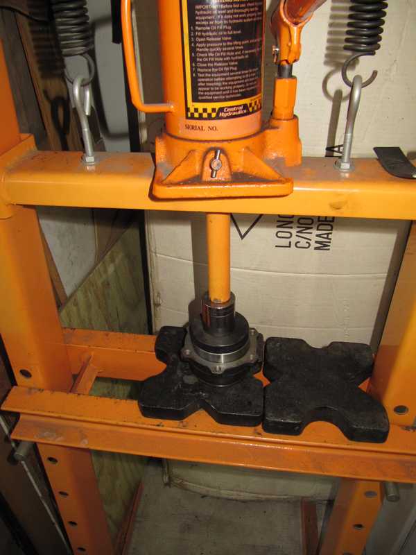
I had already tried to separate the hubs and axles with my 12-ton press; no luck there. Next, I used an idea posted in the British Car Forum around the end of 2016. It was well documented with a description and pictures, and it seemed a promising way to proceed.
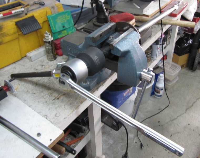
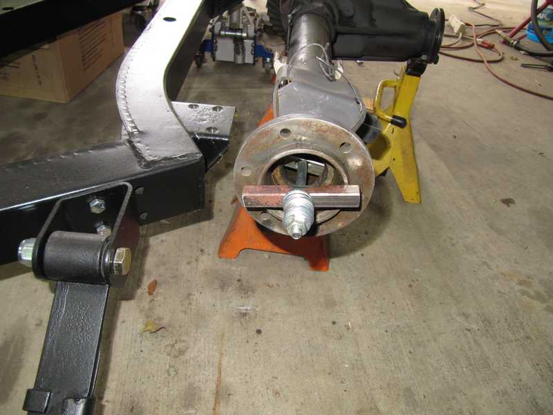
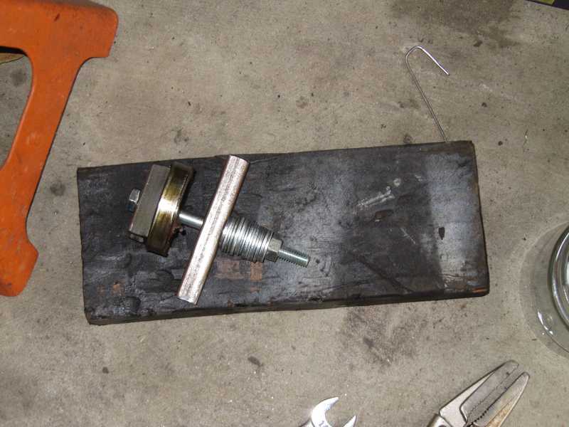
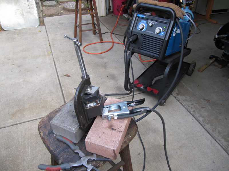
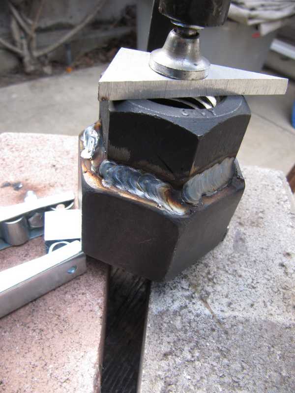
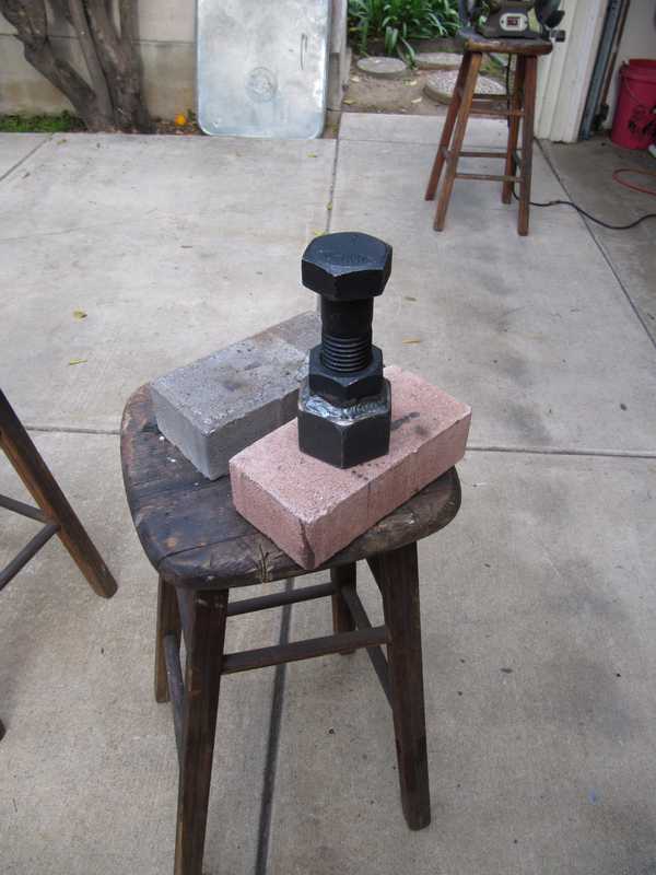
The idea is to use a nut that fits the 1-7/8 inch, 8 TPI threads on the hub and a 1-1/2 inch, 6 TPI bolt as a press. A nut that fits the latter bolt is welded to the former. This approach differs from most, which use the wheel studs to attach the puller and thus may risk damaging the studs or warping the hub. I considered using a smaller bolt with finer threads, which might put more force on the axle, but eventually decided to make it exactly as the original. It worked for the fellow who invented it, so it should work for me.
How much force can this apply? My hydraulic press can apply 12 tons; clearly, I need more than that. A derivation for axial force in screws is given in the Bosch Automotive Manual, 6th edition, pp. 292-5. With 200 lb. ft. of torque and a frictional coefficient of 0.15, the axial force is only 14,000 lbs, well below the capabilities of my press. Interestingly, reducing the thread pitch, which would make a large difference in the absence of friction, has only a minor effect on the axial force when friction is included. For all you fellow geekoids, here is a pdf of a Mathcad page showing the calculation.
I wish I had realized earlier (like, before I made it) that the capabilities of this tool were so limited. Still, the idea has quite a bit of traction by now, so I think it's worth describing my experience with it. It's also worth noting that the factory tool had the same limitations.
Although my welder can operate on either 110V or 220V AC electricity, I didn't have 220V in my shop at the time I made the tool. I was a little worried that the big slug of metal, in the form of the two nuts, would be too much for a 110V welder. I shouldn't have worried; my welder made a nice weld. The welder, by the way, is a Millermatic 211, which I bought shortly before doing this work. I'm very pleased with it.
How well did it work? Not well, alas, at least for these axles. I used a 3x torque multiplier and a hardened, 3/4-inch-drive socket, applying upwards of 300 lb ft of torque at the nut. In an attempt to break the joint loose, I also whacked the torqued screw with a small sledge hammer; the screw has a few mils of looseness and, per the original article, there should be enough motion to loosen the joint. But, there wasn't.
I think that an improved tool would have the smaller nut loose but retained. The screw and nut would then have enough axial motion that the joint could be loosened when it was hit with a heavy hammer. The trick to loosening these joints is probably impact force, not static force. I suspect it's much like breaking the tapered joint in a tie-rod end, where a tie-rod remover alone often can't apply enough force to break the joint, but it comes loose after a whack with a hammer.