![]()
Transmission and Overdrive
I have a fair amount of experience with early Porsche "901" transmissions, but I had never dug into a one from a British car. Fortunately, though, much of my experience with 901s was relevant to the TR transmission, even though the two are very different beasts. Most satisfying, parts for the TR, compared to the Porsche, are dirt cheap.
Click on any picture to see a larger version in a new window.
Contents
- Resources
- Transmission
- Overdrive
- Mating the Transmission and Overdrive
- Testing the Overdrive
- Solenoid Installation and Adjustment
Resources
The web hosts a lot of very good information on TR transmissions, so I see no point in going into a lot of detail here. The intent of this site, anyway, is to document my TR4A restoration, not to be a tutorial. For specific information on restoring TR transmissions, see the following:
- Buckeye Triumphs, the Gearbox page. There are articles on Gearbox Overhaul and Overdrive Overhaul.
- Vintage Triumph Registry, Guide to Transmission Rebuilding and Guide to Overdrive Rebuilding. These are several PDF files, accessed from the VTR Maintenance Page. Scroll down to the Gearbox section, near the bottom of the page.
- YouTube also hosts a number of video tutorials. There are a couple especially good ones by Magnus Karlsson.
Now, back to the story.
Transmission
Despite being unspeakably dirty, the transmission actually was in decent shape. After taking it apart and checking everything, I could have cleaned it and put it back together as it was, and it probably would have worked fine. A few parts were marginally out of spec, but not enough to have made a noticeable difference. Still, I replaced anything that was at all questionable, and I put a new set of synchros into it. I wanted it to work well for the long term, not just a few thousand miles. In the end, it worked very nicely.
Disassembly and Inspection
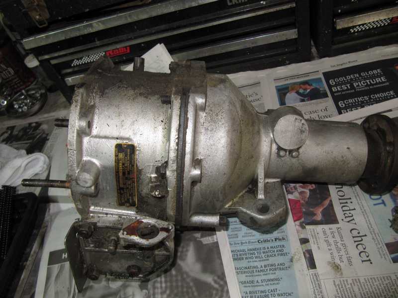
The first step was external cleaning. The usual: brush with solvent, scrape, repeat. Eventually, it came clean.
![]()
![]()
I really don't enjoy this kind of work, but I have to admit that the results are satisfying.
![]()
![]()
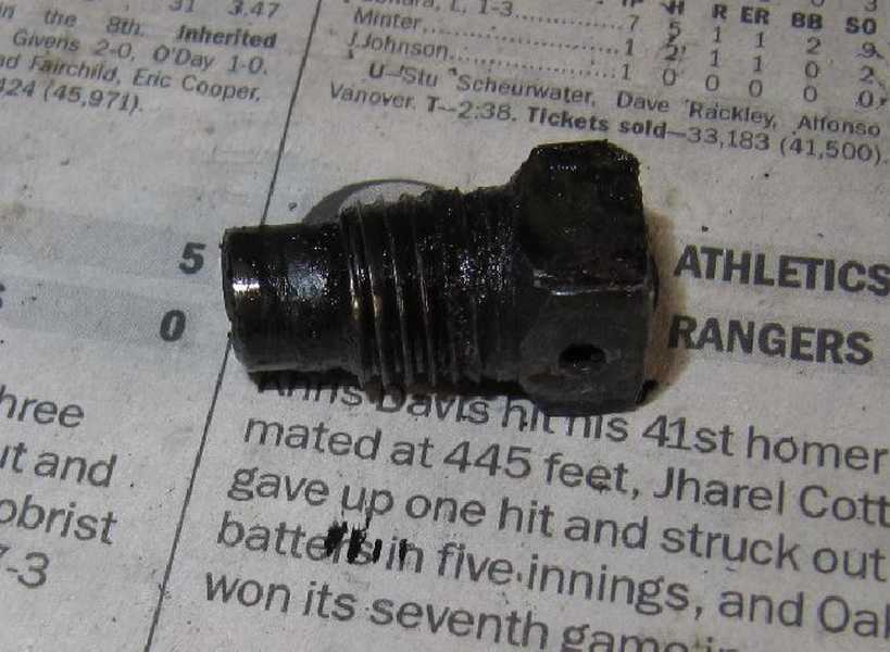
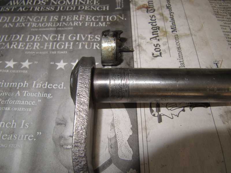
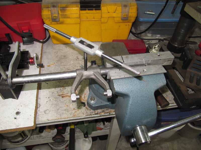
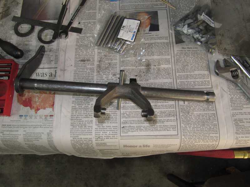
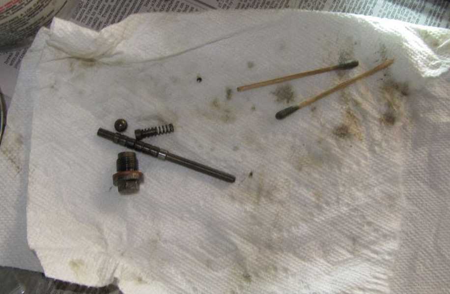
The first step in tearing down the transmission was removal of the clutch fork. The fork's fixing bolt, shown below, was broken; this is common in TR transmissions. The problem is with the bolt's long pin, which goes through the cross-shaft and into the fork body on the opposite side. On that far side, however, the pin does not fit closely in the fork, so only the near side supports forces. Eventually, the pin fatigues and breaks.
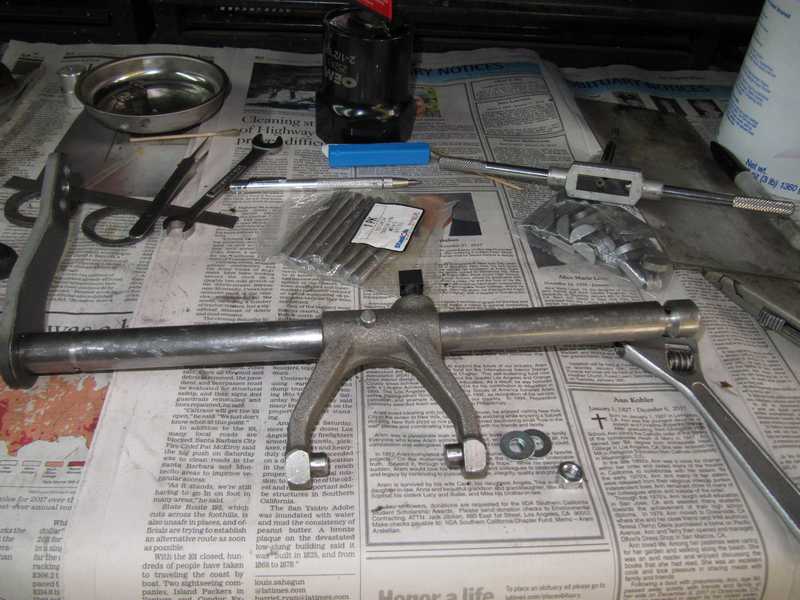
I had to extract the remaining piece of the pin before I could remove the cross-shaft. After trying the usual tricks, I gave up and cut the shaft. That's probably the best approach; new shafts cost only about $35. On reassembly, I added a taper pin for greater strength.
After removing the pieces of shaft, it became clear that I never could have removed the broken piece any other way. I had to drill it out, and because the edge of the hole in the shaft was distorted when the pin broke, I had to press the shaft out of the fork. I noticed also, when I removed the front cover, that the input-shaft seal was installed backwards. Sigh.
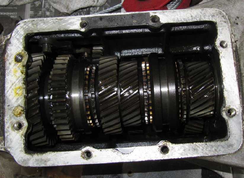
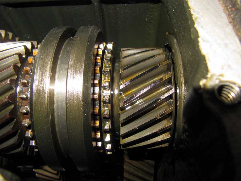
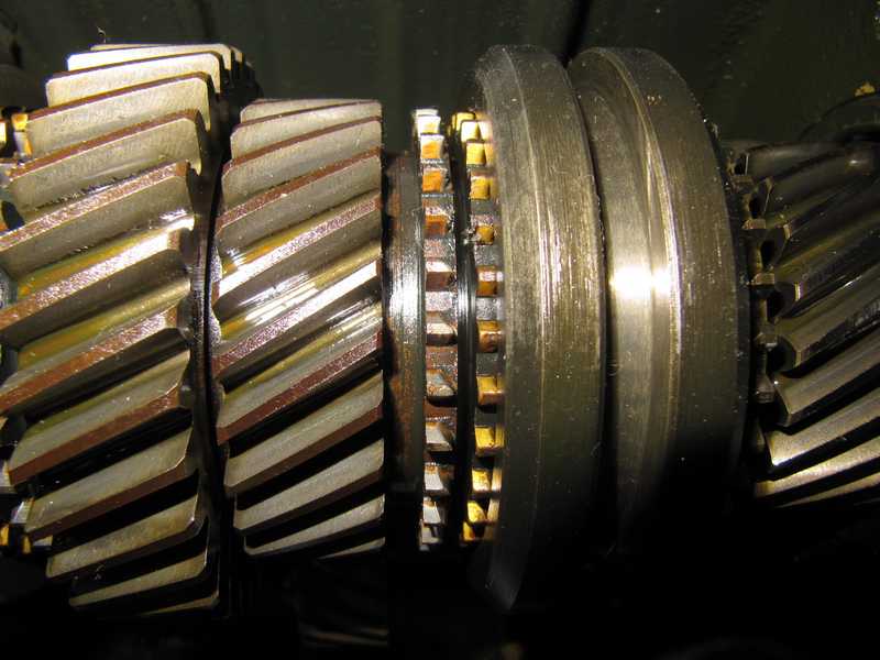
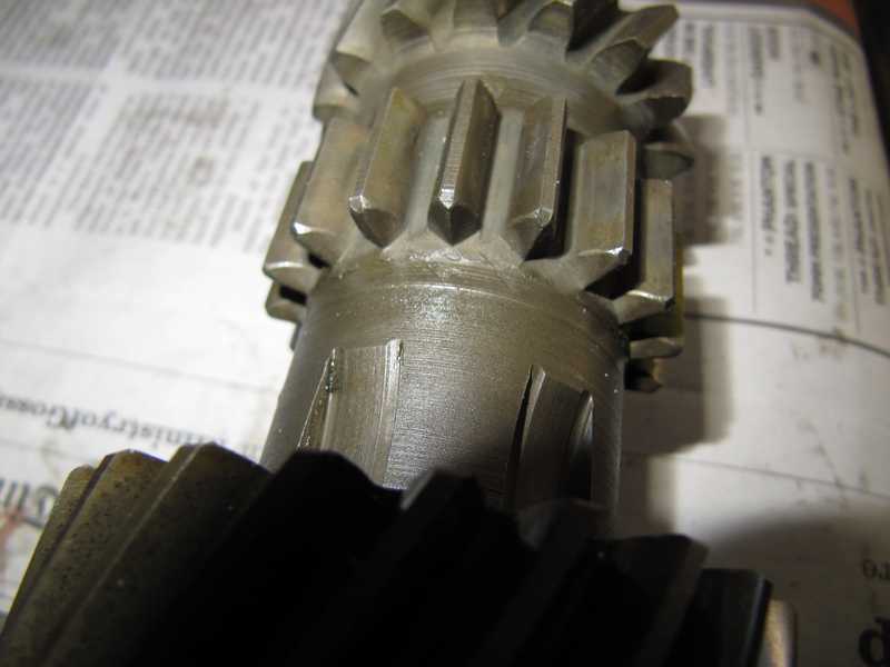
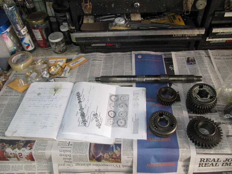
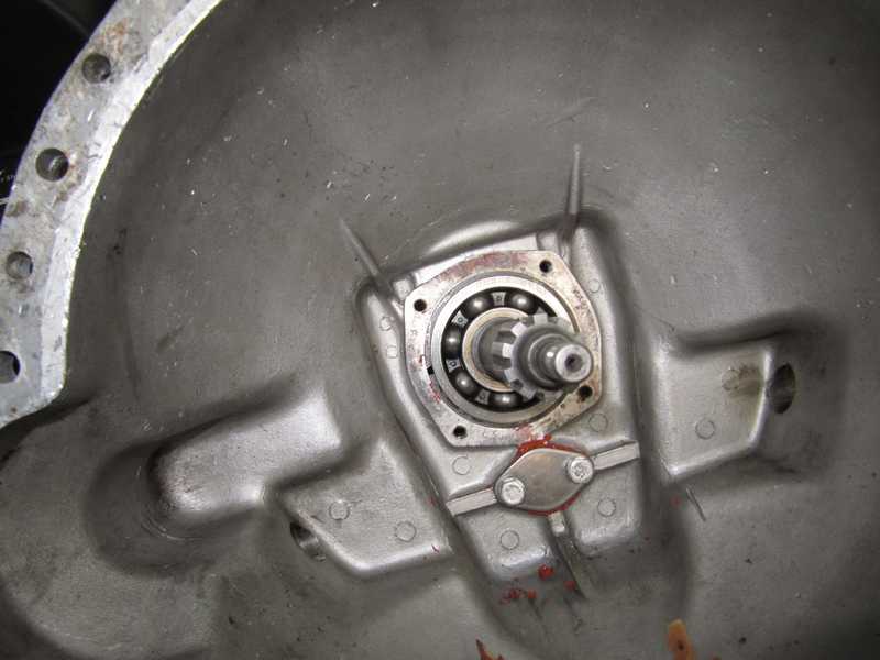
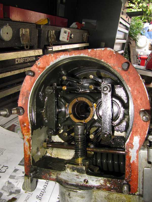
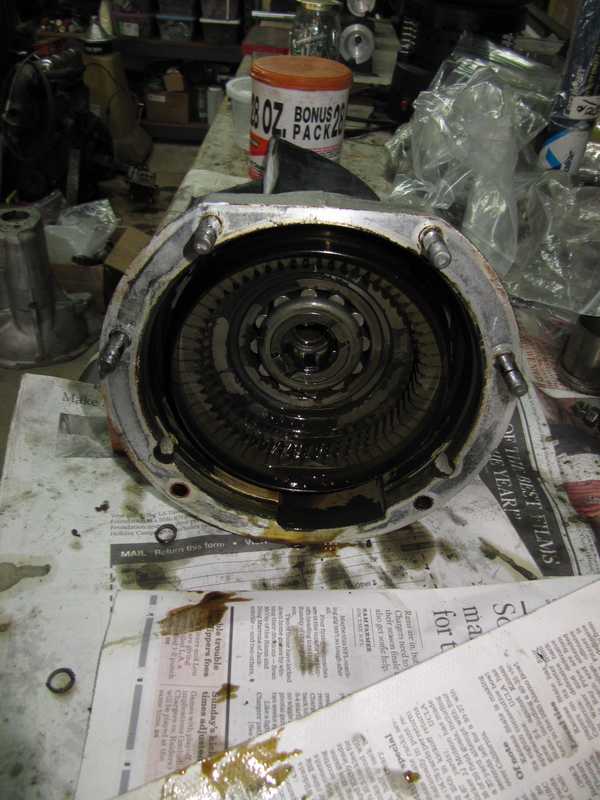
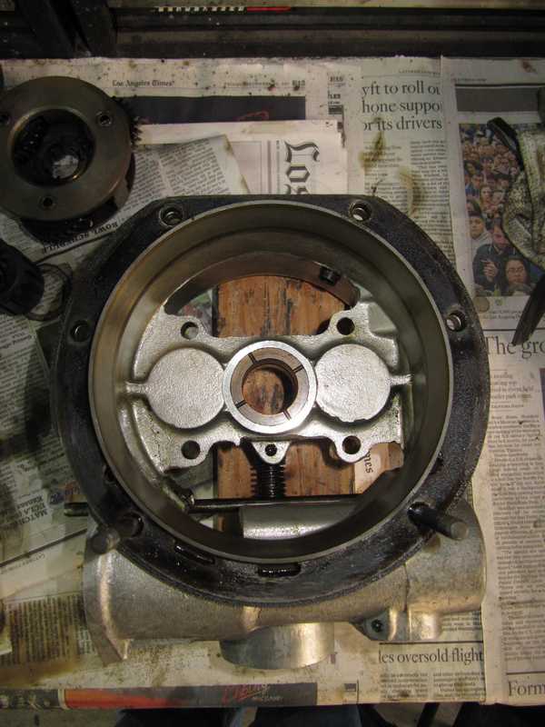
I took off the cover and got my first look at the gears. I measured the clearance between the synchros and their respective gears. The clearance should be at least 30 mils; it's a good indicator of wear. First gear was a little under that value (no surprise; it gets the most wear), but the rest were OK, 34-36 mils, about what they are when new. At first, I thought that the asymmetrical profile of the gears' synchro teeth was an odd type of wear, but I concluded that they were made that way, as (1) many transmissions for American and Asian cars also have asymmetrical teeth, so it's not unusual, and (2) all the pictures of TR gears I found on the internet showed similar asymmetry. However, I have since been told that TR transmissions originally had symmetrical teeth, and the asymmetry is from wear. Whatever the case, once the box was again in service, it worked very nicely.
The teeth on the first-reverse slider looked good, as did the those on the reverse idler. They are often chipped.
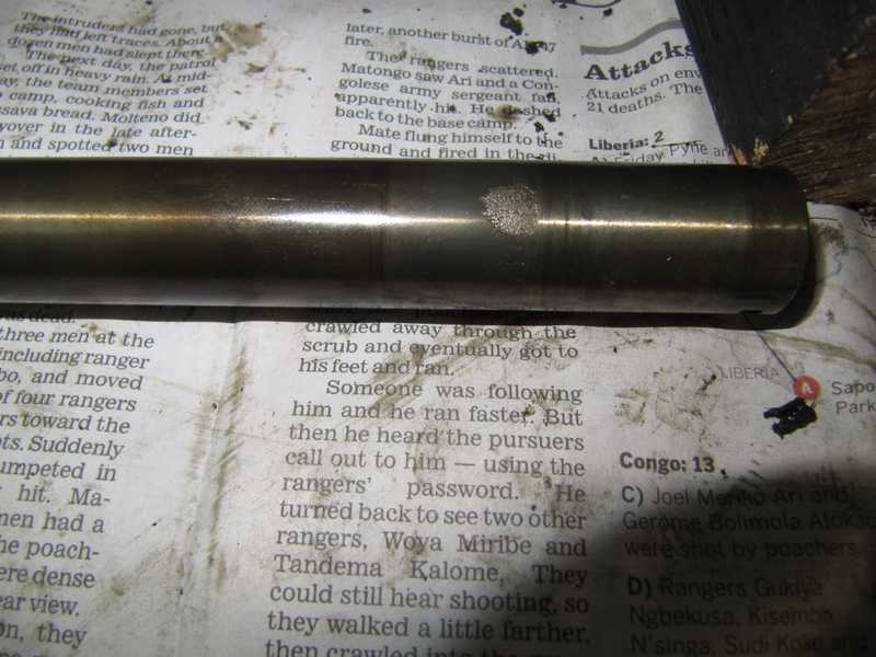
Once the stuff in the bell housing had been removed, I unbolted the overdrive and adapter plate and set them aside. At that point, the transmission's innards could be extracted. First, the countershaft had to be pushed out to the rear, allowing the gear cluster to fall into the bottom of the housing. That was necessary to create room for removing the mainshaft. I found a small spot of corrosion where the first-gear needle bearings rode. That is a common wear point, and it shows that the shaft is close to the end of its life. This is a recognized problem with the countershaft, so I replaced it with an uprated one from The Roadster Factory.
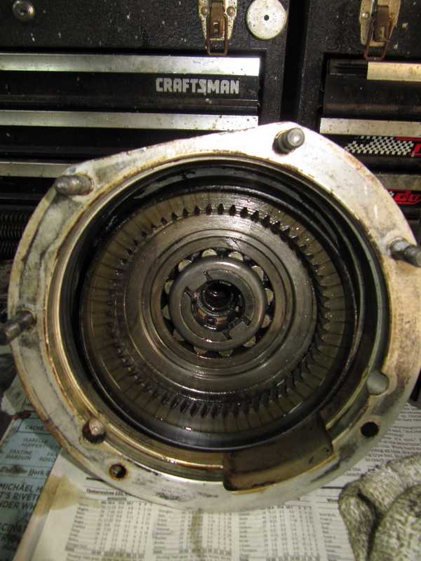
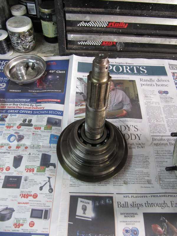
To remove the gears on the mainshaft, the two large bearings had to be removed. These were easier to remove than the documentation implied. The input bearing was removed along with the first-motion shaft by tapping out the bearing from the inside with a drift. The bearing was not a tight fit in the housing, so it came out easily. That gave me my first view of a synchro and mating cone. They looked good, but that's no surprise, as top gear in any transmission never experiences a downshift, so it usually has little wear.
![]()
![]()
To remove the rear bearing, the mainshaft is pushed forward until it is loose from the bearing. The bearing then can be pried out easily by placing a screwdriver blade under the outer retaining ring; there is a convenient recess for this at the top of the bearing. That loosens the mainshaft and its pieces, which then are simply lifted out. That's the theory, anyway.
Getting the mainshaft out was a little tricky. I used a press, but that allowed the parts on the mainshaft to fall forward. It's really necessary to tie them up with some wire, or else they interfere with other parts inside the case and can jam the mainshaft as it is pushed forward. The bearing was fairly tight on the shaft, but not in the housing. Once the bearing was out, lifting out the cluster of gears was easy. The bearings looked fine; I saw no reason not to reuse them.
![]()
![]()
![]()
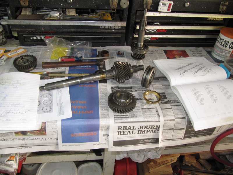
The slider came off the front synchro hub and I lost one of its balls. No problem; it's just an ordinary, quarter-inch ball bearing, and I have a stock of precision, grade-25 ball bearings that I keep for bicycle work.
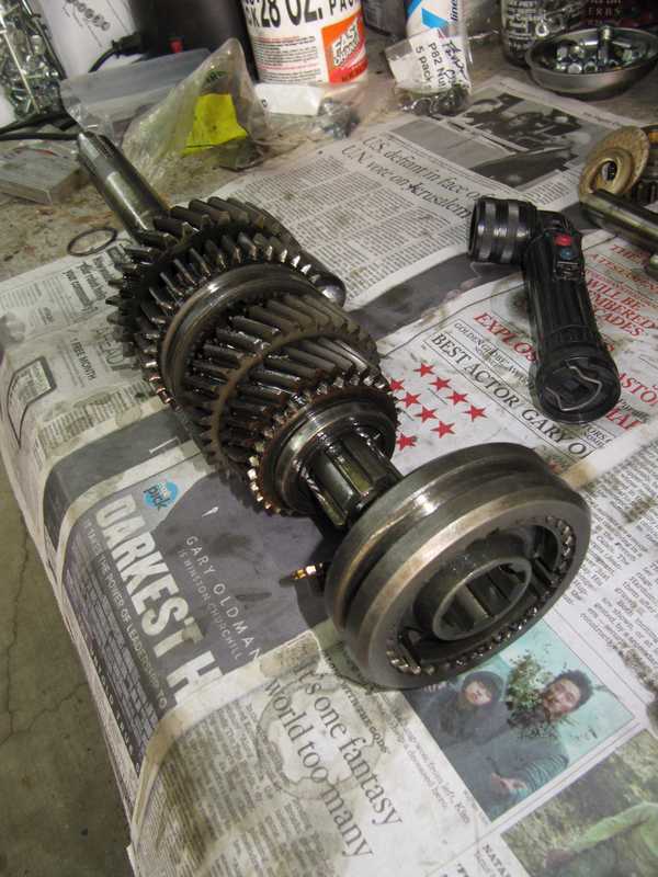
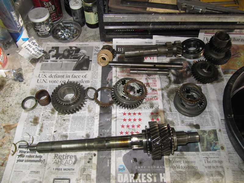
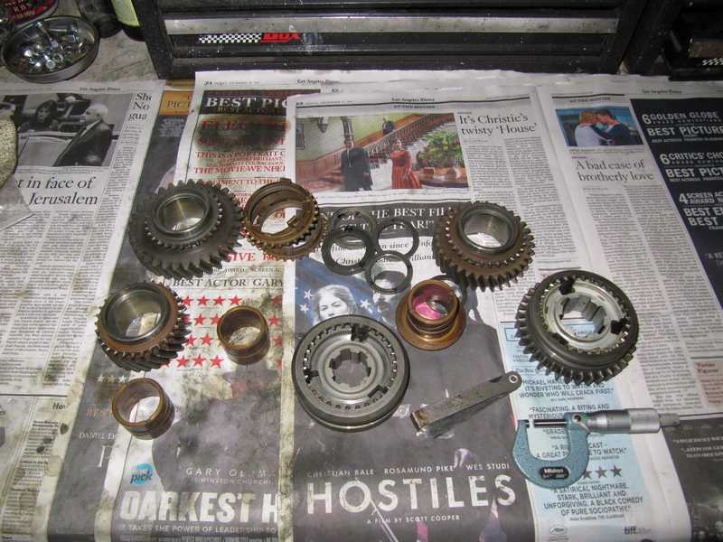
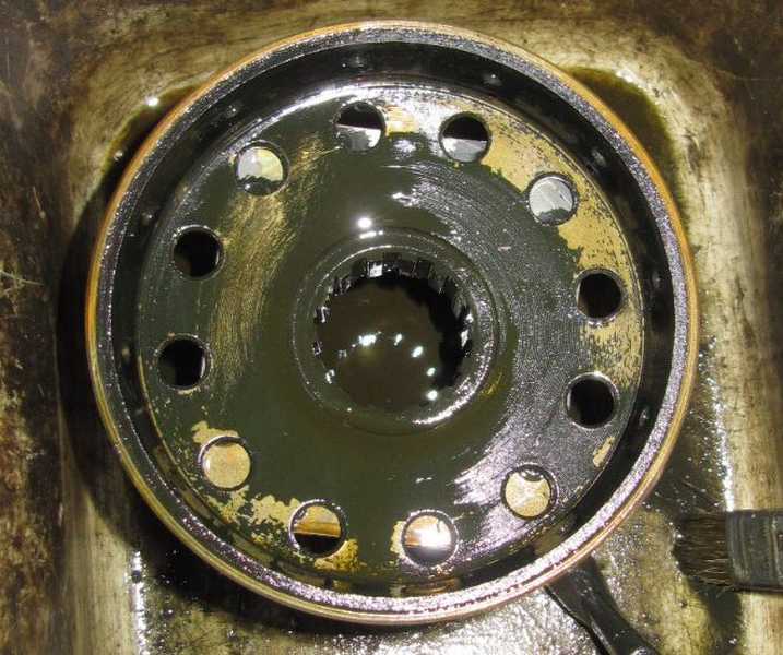
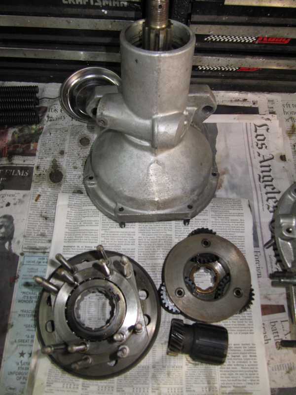
The cluster gear, which the manuals call the laygear, was just lifted out, but it was necessary first to remove one of the thrust washers. That left me with a nice pile of gears, bearings, and spacers. The black substance on gears and the inside of the housing is a deposit from worn-out oil; I have read that it is simply carbon, reduced from oil as it breaks down. The oil clearly had not been changed often enough. On the whole, though, the transmission looked pretty good. As a minimum, I needed to replace the first-gear synchro, the countershaft, and ordinary things like seals and gaskets. And clean everything well, of course. With new parts and fresh oil, it should work nicely.
![]()
![]()
Most of the gears just slid off the main shaft. I cleaned parts as they came off and labeled them for reassembly. Second and third gears are held on by a snap ring; there is a special tool for removing it. Without the tool, it's reputedly difficult to remove, as it sits in a recess that restricts the amount it can be bent outward.
I discovered a trick, with a couple screwdrivers, that made it easy. With the first screwdriver, I pried one end of the snap ring away from the shaft, then used the second screwdriver to lift it out of the groove and onto the splines. I kept that latter screwdriver in place and put the first one two slots away from the first, not in the adjacent slot. Again, I lifted the ring out of its groove, moved the second screwdriver, and proceeded around the shaft that way. Special tooling? We don' need no stinkin' special tooling!
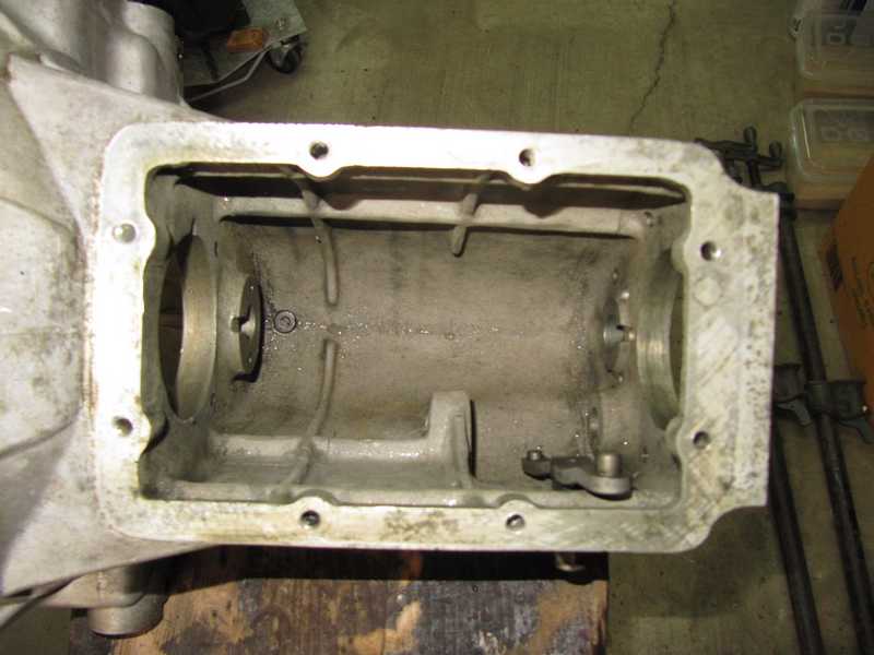
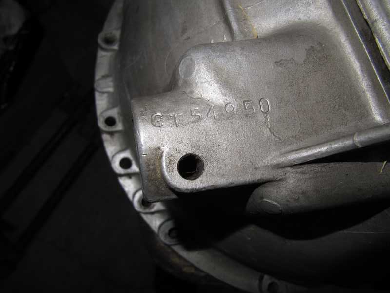
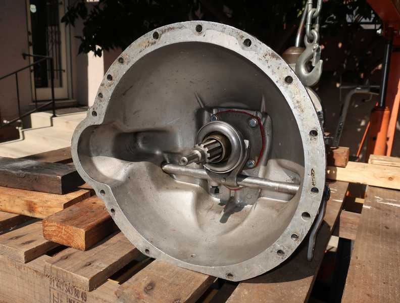
I cleaned the case, first with solvent and then with detergent and a pressure washer. It looks a bit cleaner now, I think.
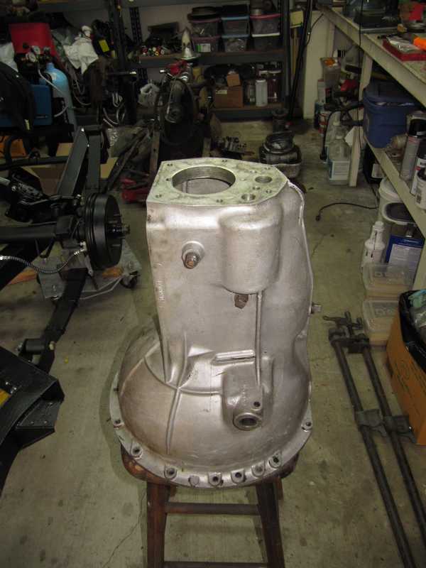
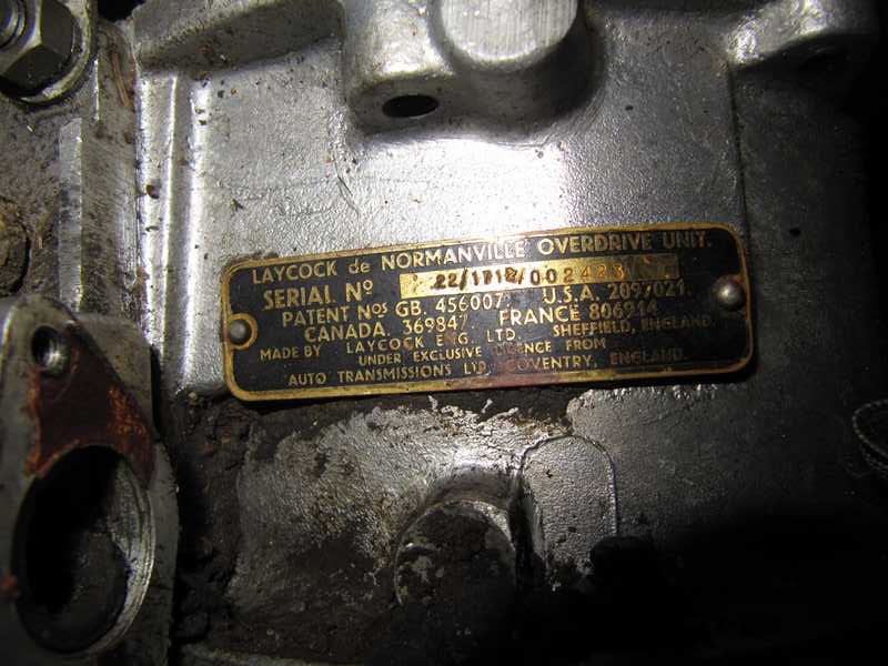
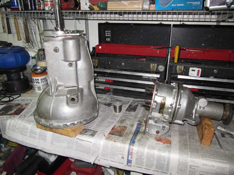
While I was at it, I noted the serial numbers of the transmission and overdrive. The transmission's serial number is very close to the car's commission number, indicating that it is almost certainly original. The Laycock Type A overdrive is the widely used 22/1712 model, correct for the solid-axle TR4A. (The IRS cars had a different model, but the only difference was in the accumulator pressure setting.) Unfortunately, the serial numbers were applied by Laycock, not Triumph, so there is no way to know for sure that the overdrive is original to the car. Other indications, however, such as date codes on its parts, indicate that it is likely to be original.
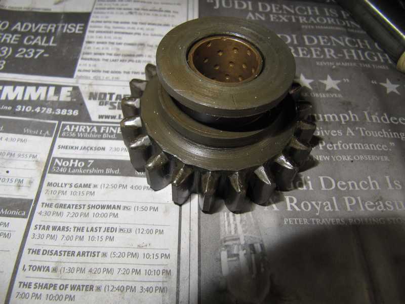
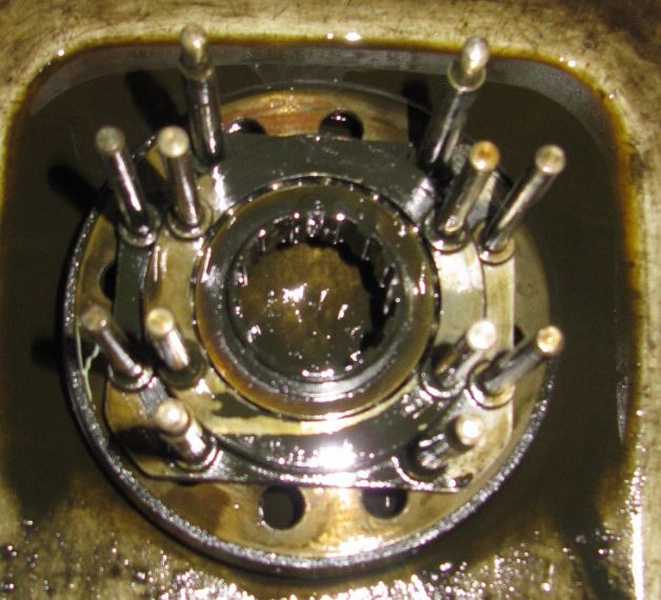
Determining what I needed to buy required some measurements, all of which were well described in the shop manual and in the documents listed above. The first was the gear float, the protrusion of each brass bushing past the edge of its respective gear. The spec is four to six mils. Mine were all at the lower end of the range, but within spec. Another is the float of the second- and third-gear bushings, mounted on the shaft, and finally the same for the first-gear bushing. The float was adjusted by selecting thrust washers of various thicknesses. The second-third float was 2 mils out of spec, but the first was OK. For two freakin' mils, I needed a new thrust washer!
One of the bronze bushings, which you can see in the picture above, is the so-called "top hat" bushing. It regularly comes out in pieces. Fortunately, mine was OK; it's a moderately expensive part.
Bearings
Bearings are always a dilemma. Most of the original bearings were made by Timken, a high-quality manufacturer. Well used bearings, however, can look good but be weakened in ways that are not visible. Conversely, new parts are subject to "infant mortality" failures, caused by manufacturing imperfections. Often, rebuilders simply replace bearings, even if they look good, to prevent a possible bearing failure, but by doing so, they may actually increase the chance of a failure. It's almost impossible, in practice, to know whether the old or the new bearing is more reliable. What to do?
If the transmission has old but high-quality bearings and they appear to be in good condition, with absolutely no pitting or visible wear, it is reasonable to keep them. They will be in use for perhaps another 100,000 miles, though, so they really must be visually perfect. If they are replaced, top-quality bearings are essential. The bearings from the usual suppliers of classic-car parts are often of questionable quality, made by obscure overseas manufacturers. Bearings are largely standardized, however, so they can be obtained from multiple sources. Quality bearings from well known manufacturers will be more reliable and, often, less expensive.
The problem, then, is to determine the bearing type. Most bearings, but not all, are marked with a number that is universal throughout the industry, so even if your box has old, cheapo bearings, you can still find quality replacements. They can be obtained from bearing suppliers or on-line sources; I've even bought some from Amazon.
This approach also avoids the penchant of some parts suppliers to sell bearings that are not correct replacements. One example is the 15100-SR bearing used in the differential, which is often replaced by a 15100. The latter differs from the former in at least one important dimension. This problem, discussed at the end of the Differential page, is another argument for restoring or reusing parts instead of replacing them.
These days, most bearings are made in China. Despite the stereotypes, many kinds of manufactured products come from China, and good manufacturers maintain their quality standards regardless of the location of the factory. There are two potential problems in buying Chinese bearings, however: (1) no-name bearings, or bearings from obscure manufacturers, may indeed be of poor quality, and (2) bearings supposedly from quality manufacturers could be counterfeit. To avoid those problems, I don't buy makes I don't recognize, and I stay within the manufacturer's sales chain. Buying bearings on eBay, shipped directly from China, is a good way to get a counterfeit bearing.
Needle Bearings
I had some concerns about the needle bearings, so I decided to replace them. Some rebuilders state dogmatically that they should always be replaced. I think this is probably valid for the earlier transmissions with loose needles, but I'm not sure it's always necessary for the later ones, like mine, with captured needles.
Removing the cartridge needle bearings from the countershaft and first-motion shaft is a perennial problem in restoring TR transmissions. They are tight, and conventional blind-bearing pullers often fail to remove them. The only remaining technique is to remove the needle rollers and cut a slot in the side of the bearing shell, but the shell is quite hard, so that can be difficult. That also can leave marks on the inside surface of the shaft, but since the bearings don't roll on it, a small amount of damage isn't fatal.
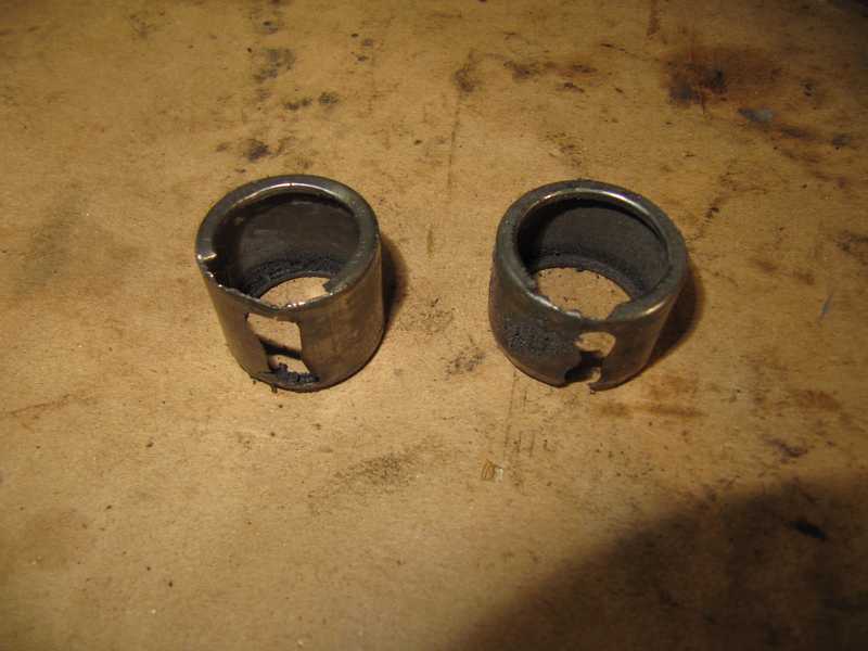
My blind-bearing puller didn't work, as might have been expected, but I still found a workable procedure for removing the bearings. Using a chisel, I first cut a piece out of the outer edge, allowing the needles to be removed, and knocked a piece out of the opposite (inside) edge. I then used a Dremel tool with a small, disk grinding wheel to grind the bearing shell from the inside. The choice of a grinding tool was important. The coarse, pink grinding wheels didn't work, but a fine-grit wheel, which looks like a thick cutoff wheel, worked well and was easy to control. To avoid grinding into the mounting surface, it was necessary to monitor the grind carefully.
The pictures below illustrate removal of the first-motion shaft bearing, but I used the same technique for the countershaft ones.
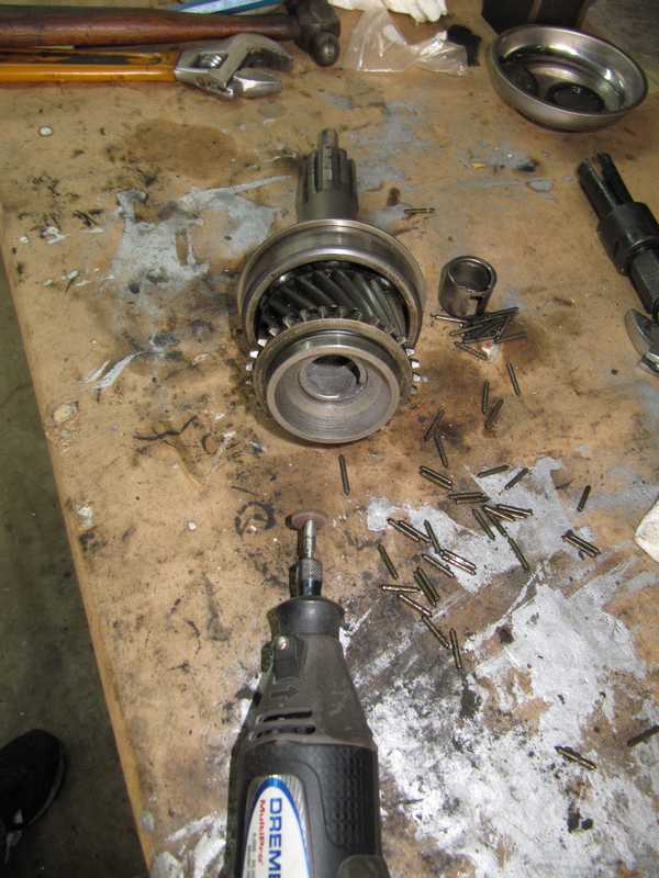
I'm still finding those ^@#! needle bearings all over my shop!
This operation left a lot of grit, which obviously had to be cleaned out. A good solvent wash was effective.
New needle bearings were installed in all three locations: one in the first-motion shaft and two in the countershaft. In contrast to the difficulty of removing the old ones, the new bearings were easy to press into place. The last picture below shows the insertion tool I made for the needle bearings, which allows them to be pressed into their respective bores undamaged. It is sized for the two smaller countershaft bearings, but worked fine for the slightly larger one in the first-motion shaft.
Reassembly
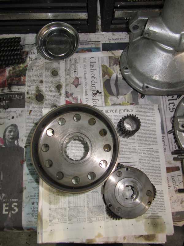
With everything cleaned and my new parts in hand, it was time to reassemble the transmission. First is the countershaft gear and reverse idler. The reverse gear and idler are often pretty beat up, but mine looked almost new.
The countershaft gears just slide together and go into the box along with their thrust washers. There is a rather broad specification for the float, which is measured with a feeler gauge. The gear's float was well within spec; if it's too great, new thrust washers usually fix the problem. To provide enough room for assembly, the countershaft itself cannot be installed until the mainshaft and first-motion shaft are in place; the gears just sit in the bottom of the box. I found it helpful to tape the reverse idler assembly out of the way, so it didn't interfere with the installation of the mainshaft. It was also important not to let the countershaft gears move around too much, as that could push the thrust washers out of position.
Next, the mainshaft was assembled. I changed a couple of the thrust washers to get the right bushing and gear float. This is the only adjustment in assembling the mainshaft; the rest involves simply sliding parts into place in the right order. I installed new synchro rings in all positions. I paid a little extra and got the high-end, German-made synchros that are available from a number of suppliers. (Once I got the car on the road, I was happy that I chose those synchros. They worked beautifully right from the start, with none of the usual initial stiffness.) I made good use of my notes from disassembly, the above-listed resources, and, of course, the shop manual.
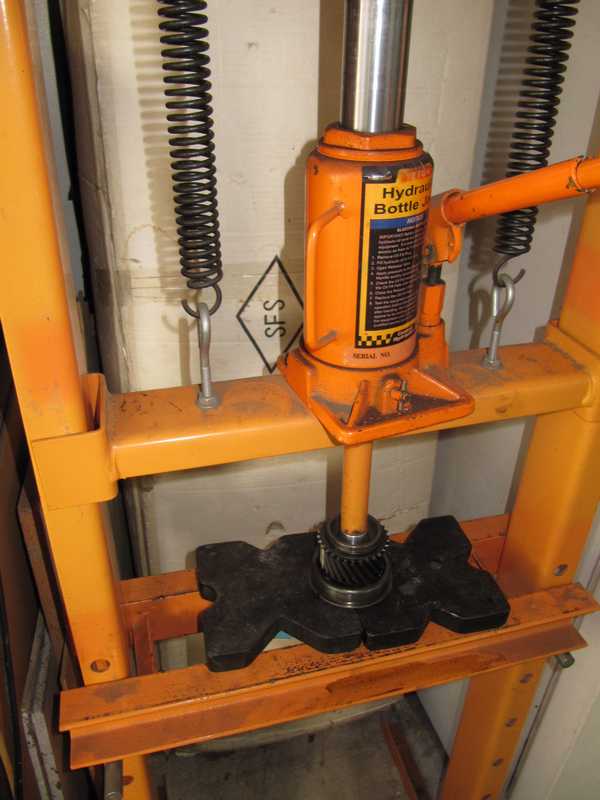
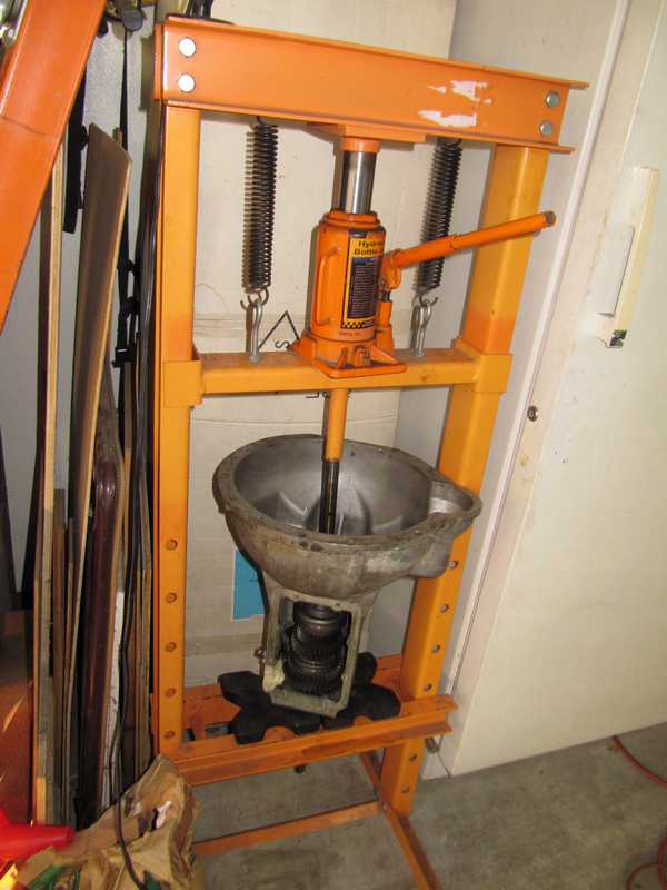
Once the mainshaft was assembled, it had to be pressed into the rear bearing. That involved putting the whole box onto the press. I used the old countershaft to extend the post of the press. Once the mainshaft was in place, I pressed the first-motion shaft into the front.
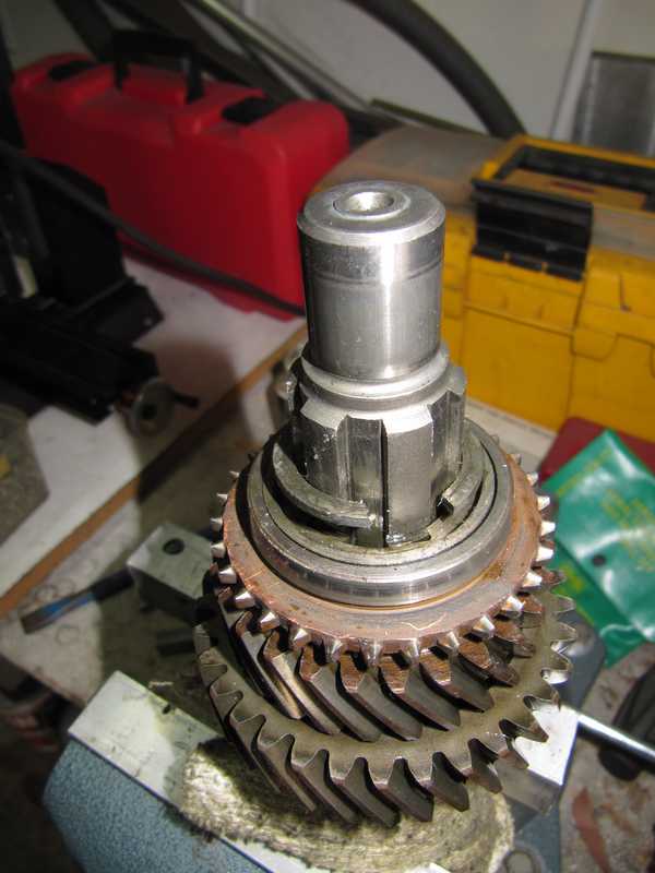
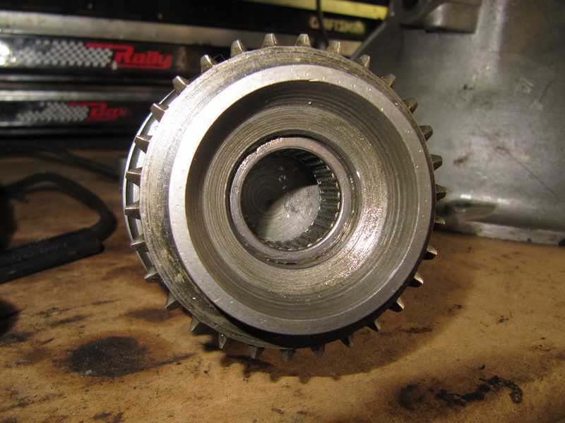
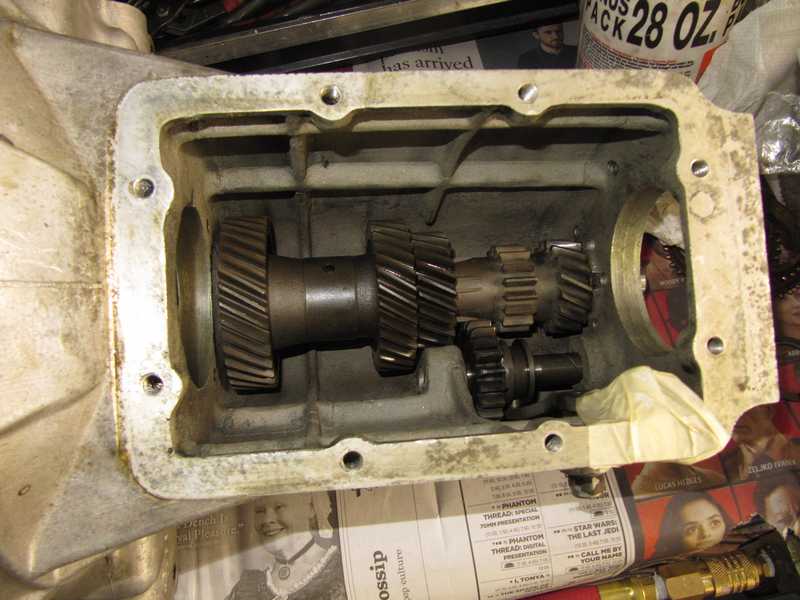
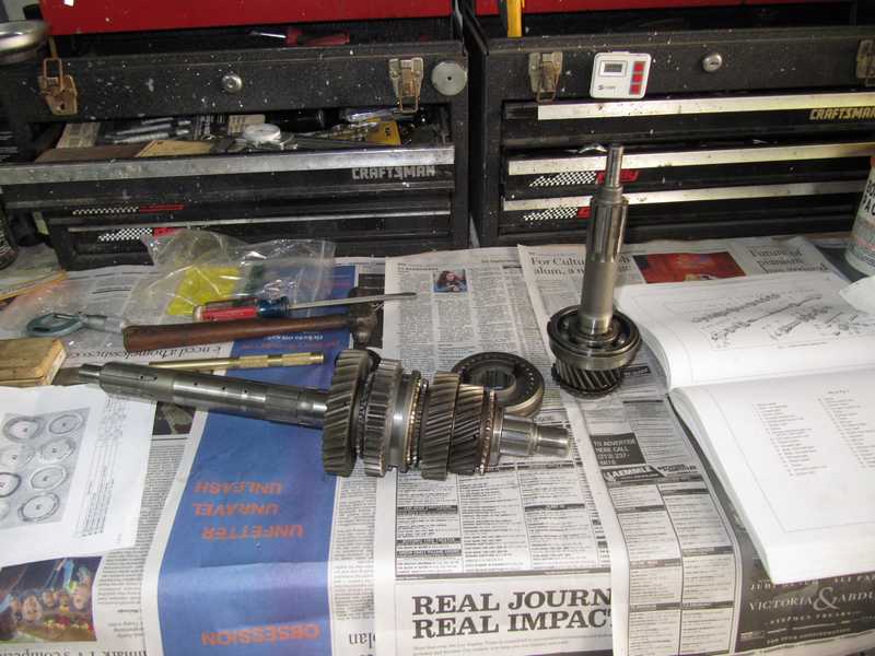
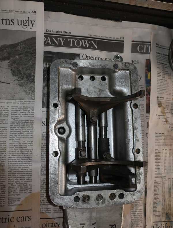
Finally, I wiggled my new countershaft into place and installed the rear plate that secured both shafts. Below is the transmission with the finished internals. The the bright brass parts are the edges of the new synchros.
![]()
![]()
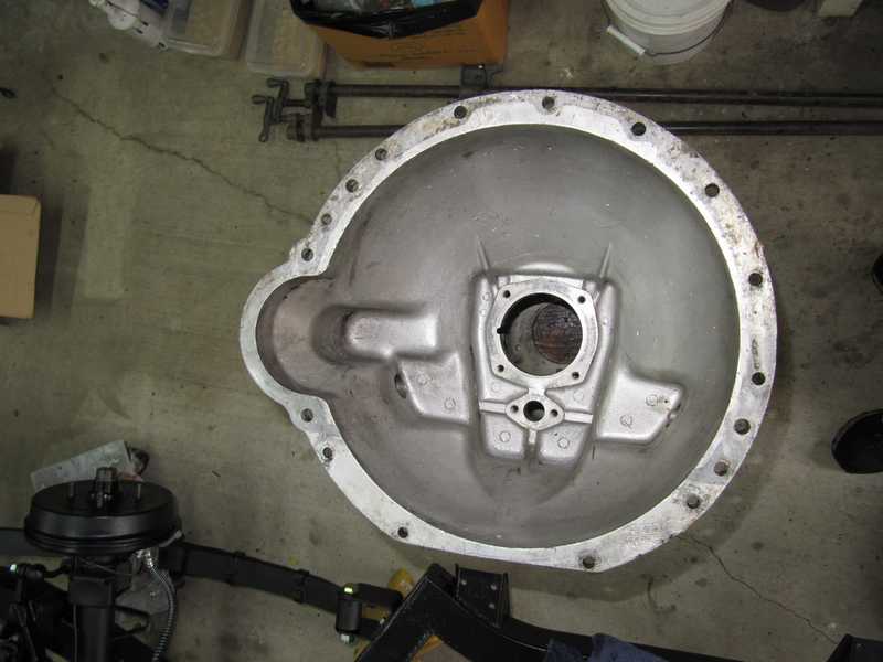
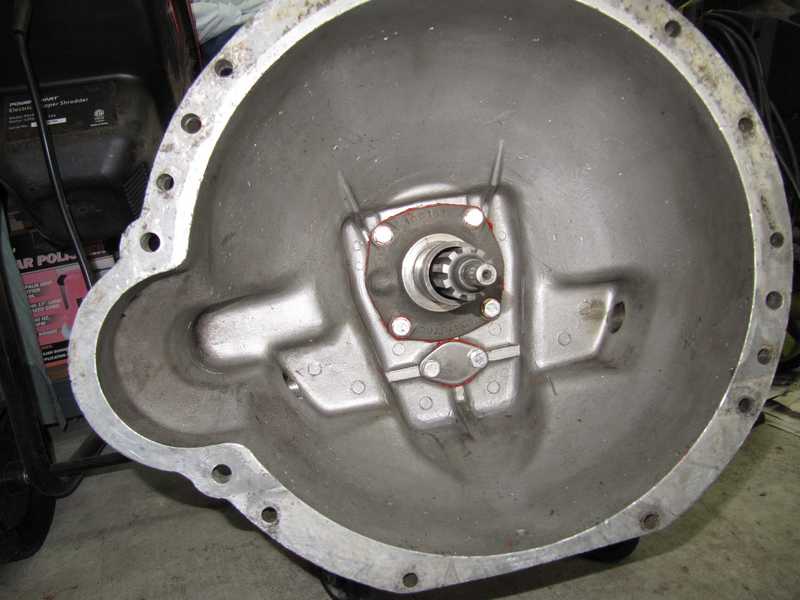
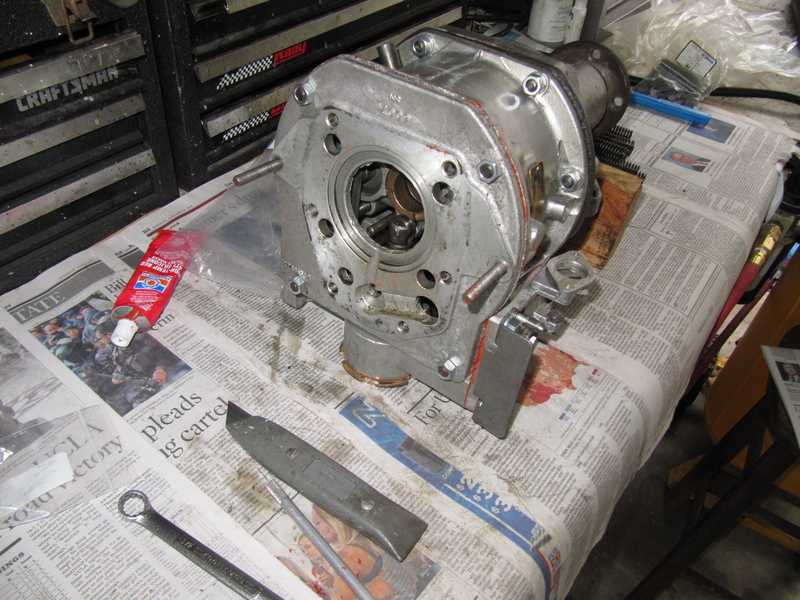
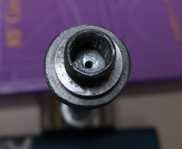
I installed the front cover and the countershaft cover with new gaskets and a smear of sealer. Unlike the previous person who worked on it, I installed the mainshaft seal correctly but, at first, I didn't install the front cover correctly. My mistake was to believe the shop manual figure shown below. The manual shows the "bump" on the flange of the cover located at the top. In reality, it should be on the left (as you face it).
![]()
![]()
This isn't the first serious error I've found in the shop manual. It's frustrating.
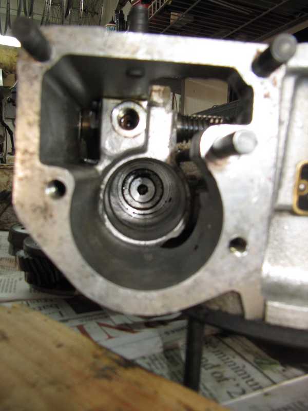
I'm still not entirely sure what that bump is for. The bump is the outer manifestation of a passageway in the front cover. It aligns with a small opening in the transmission housing (which can be seen more clearly in an earlier picture), so presumably it creates a passageway for oil to return from the front of the bearing to the transmission interior. However, (1) the bearing isn't sealed, so I don't see why oil couldn't return through the bearing itself, and (2) the opening is covered by the snap ring that locates the front bearing. One can move the ring so its gap is over the opening, as shown below, but the ring probably will move again in use, blocking the hole. Anyway, for what it's worth, it's now the way it should be.
The screw holes for the front cover go all the way through the housing, so it is important to seal them well. I put a little sealer on the screw threads. I also used copper washers under their heads; that's traditional, but it seems unlikely that one could torque the bolts enough to crush the washers and get any additional sealing from them.
The transmission was ready to be mated to the overdrive; that process is described in the section Mating the Transmission and Overdrive.
Clutch Shaft and Release Bearing
I installed new bronze bushings for the clutch shaft. The old ones were steel and too small; I think they may have been TR250 bushings. As a result, they wore a groove into the old cross shaft. The correct bronze bushings are softer and much wider, so they probably will prevent that. Occasional lubrication should help a little, too.
There is a lot of angst among TR owners, with justification, over broken clutch-fork pins. One of the better methods for fixing the problem, which I chose, is to install a no. 5 taper pin to strengthen the attachment of the fork to the shaft. With the original pin in place and tightened, I common-drilled the fork and shaft, then reamed the hole with the appropriate taper reamer so the pin was approximately centered in the fork.
I cut off the excess pin length, ground the ends smooth, and threaded the narrow end for a 1/4-inch UNF nyloc nut. I was careful to make sure that the threads stayed outside the fork, so the solid pin spanned the entire joint, allowing both ends of the pin to support the forces on the fork.
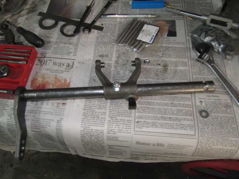
The pin is inserted from the front with the nut in the rear. At first glance, it seemed that the pin might be easier to install or remove with the nut in front, but that meant the pin itself had to be inserted from the rear. I didn't think there was room for that, and it turned out that there wasn't. I put the parts on the shelf until I was ready to install the transmission.
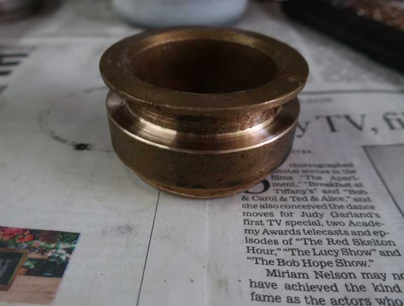
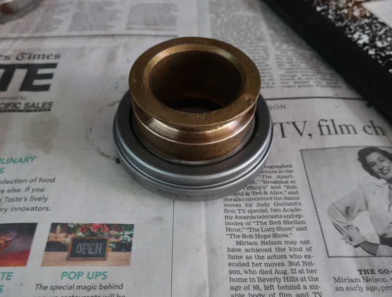
The brass bearing bushing was OK, but, to smooth it off, I turned down the surface that mates with the fork. I then pressed the new release bearing onto it.
(Once the car was on the road, it exhibited a little light clutch "judder." After checking the usual causes, such as loose engine or transmission mounts, I was unable to eliminate the problem completely. One possible cause is wear in this piece, not unlikely, in view of its age. If I ever have to pull the transmission, I will examine it more closely.)
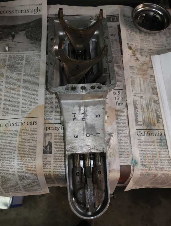
Below, all the pieces are assembled.
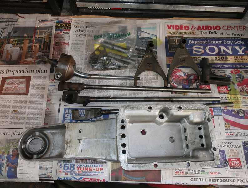
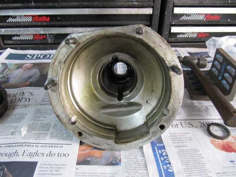
Shifter Assembly
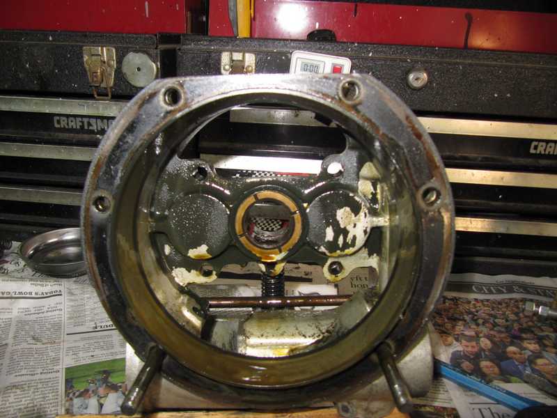
I disassembled the shifter assembly. I was most concerned about the o-rings, as they probably have never been replaced, and they are essential to prevent leakage. I also wanted to check the balls and springs and to make sure that the release force was right.
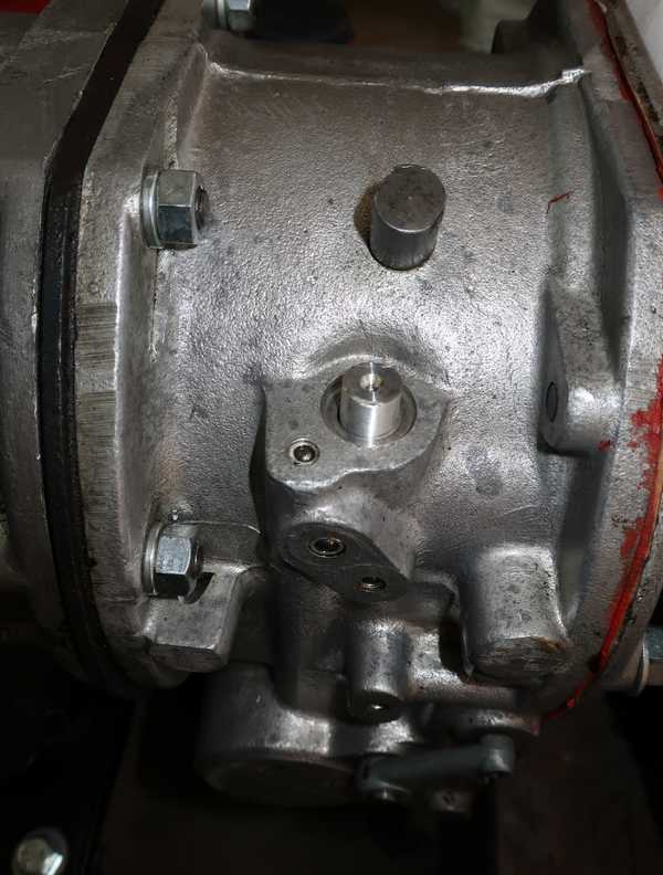
The o-rings, mounted in the three holes in the picture below, were in better shape than I had expected. Still, best to replace them. The new o-rings didn't fit perfectly, as (I later learned) the originals were square in cross-section and are no longer available. A common trick is to make washers to fit under the o-rings, increasing their compression.
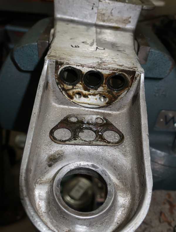
The set of balls and springs shown below helps to hold the transmission in gear. Each set fits into its adjacent hole in the shifter body. Another set of two balls and a small cylinder provides the lockout function; those parts are not visible in the picture. Early shifters used balls and large springs on both the 1-2 and 3-4 shift rods, but my later shifter uses a bullet-shaped piece on the 3-4. I don't know if the rods are different.
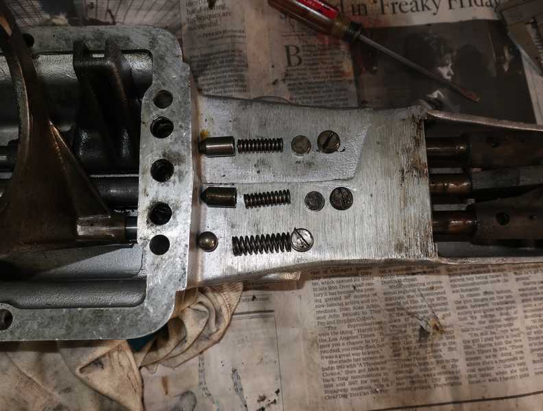
I cleaned the disassembled shifter and all its parts. The forks are attached to the shift rods by square-headed screws, which are tough to remove without a special socket. The ends, which are attached by identical screws, need not be removed from the rods.
Reassembling the shifter was straightforward; I just followed the instructions in the shop manual. I replaced the balls and o-rings, but kept the springs, as they looked good. I readjusted the release forces to the spec in the shop manual.
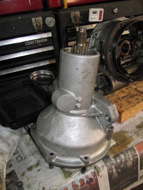
Overdrive
The solid-axle TR4A used a Laycock de Normanville Type A overdrive, model no. 22/1712. The one on my car was almost certainly the original, as it was the correct model, had appropriate date codes, and showed no sign of previous service or replacement. The IRS cars used a slightly different model.
Unless an overdrive is damaged, the only parts likely to need replacement are the bearings, seals, and perhaps a couple of springs. I didn't expect to have to do more than that, as the overdrive was in working condition when I received the car.
Disassembly and Inspection
As with the transmission, the inside contained worn-out oil and was covered with black deposits. The deposits were thin and unlikely to be a problem (but I cleaned them out anyway). Sludge is more of a concern; I found a little under the filter screen in the pump.
The rear flange was surprisingly difficult to remove; I had to use a puller.
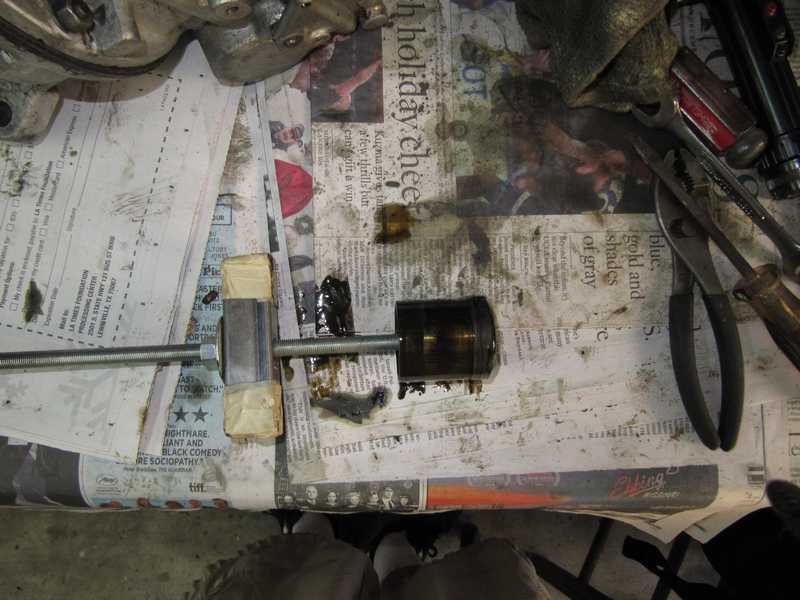
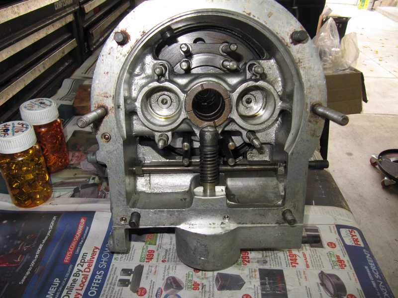
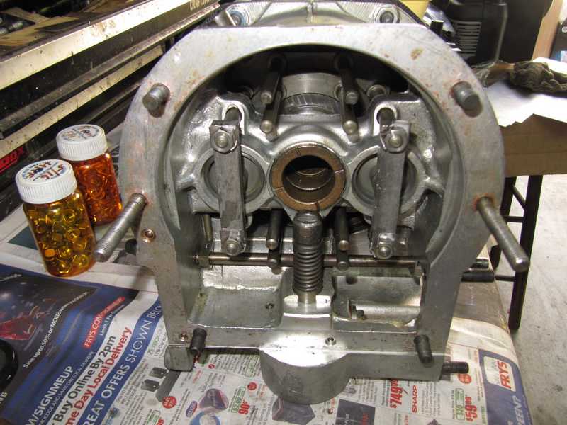
I removed the accumulator springs and piston so the accumulator chamber could be cleaned. To remove them, the mounting flange for the solenoid first had to be removed. The spring was huge and strong, but the flange bolts were long enough that the spring was uncompressed by time they were free of the case. The accumulator piston has a reputation for being difficult to remove; typically, some kind of puller is needed, often just a long, 3/8-inch UNF bolt that threads into a hole in the piston. I used my front-suspension compressor as a puller, but the piston, to my surprise, came out easily.
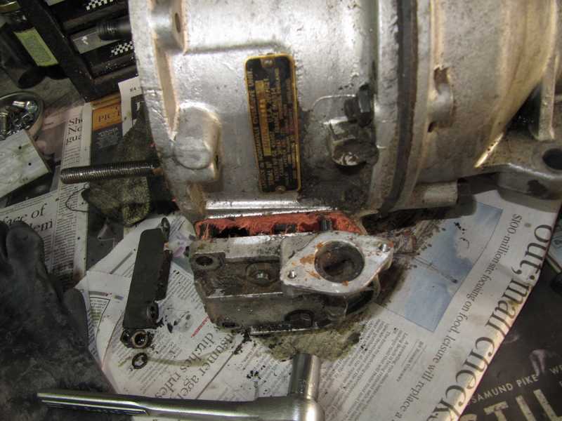
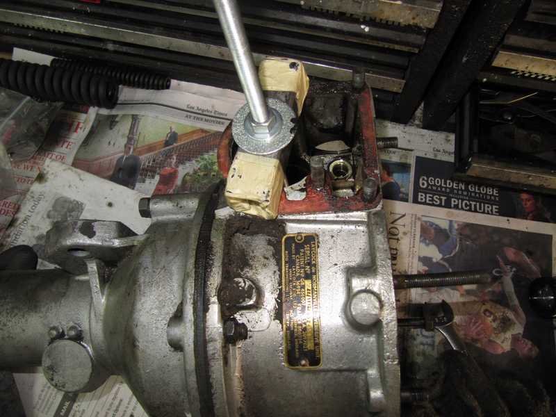
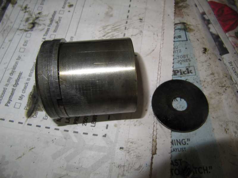
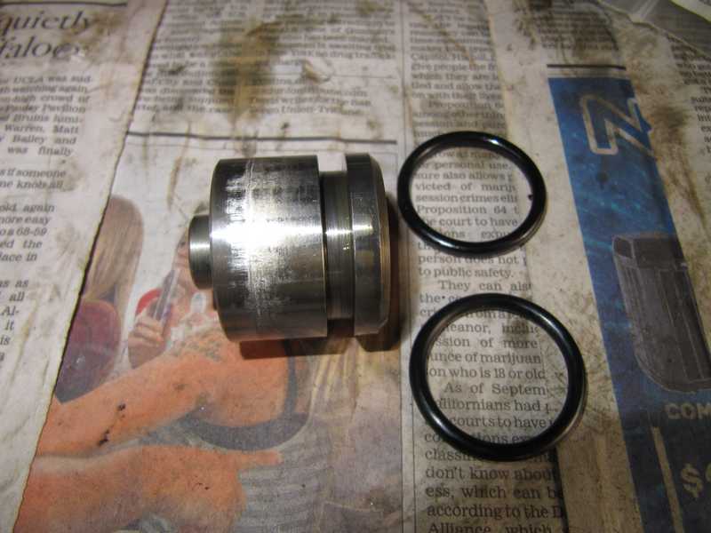
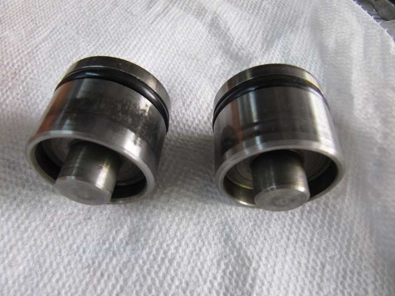
Here is the accumulator piston; first, as it came out, and in the second picture, cleaned. The piston in this model, much like engine pistons, has metal sealing rings; other models of the overdrive use rubber o-rings. That large washer is used as a shim to adjust preload on the spring, which sets the hydraulic pressure.
I removed the operating pistons and cleaned the interior as well as I could at this stage. Those pistons had rubber o-rings, which had hardened, so they had to be replaced.
The pump was very tight in the housing. I chose not to remove it, as it worked smoothly, the clearances seemed good, and I felt there was considerable risk of damaging something if I tried to extricate it. Just one of the judgment calls you have to make in a project like this.
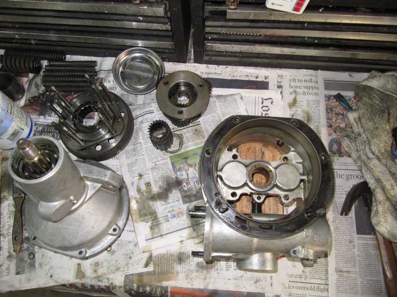
With some difficulty, I separated the halves of the overdrive. More black deposits were visible. The first photo below shows the annulus and unidirectional clutch; the second shows the forward housing viewed from the rear.
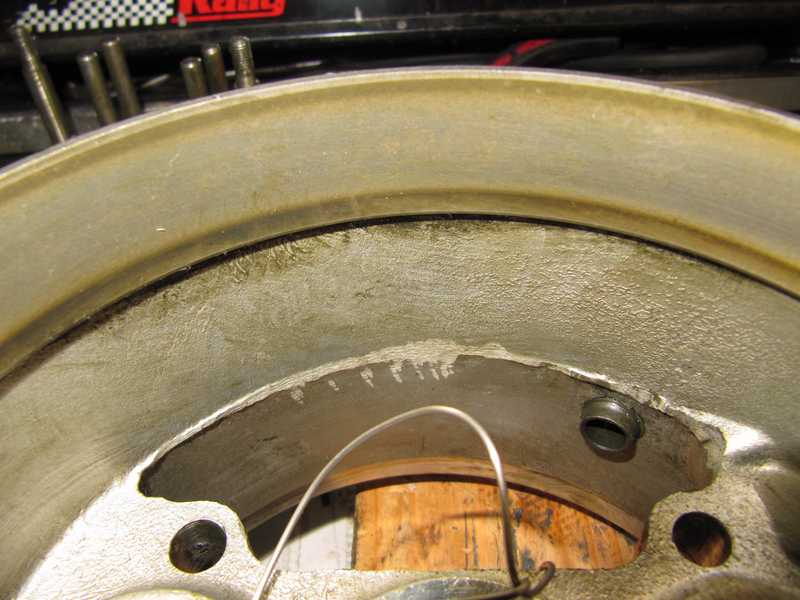
Below are the thrust ring and sliding member, as I started to clean them. Lots of black crud. Fortunately, the clutch surface looked good. Replacing it is a painfully expensive job.
Although those black deposits were ugly, they were easy to clean off. Below, the front part of the housing (rear view), the annulus, and the rear housing.
Below, some pictures of the overdrive, partly disassembled, and some of its pieces. I didn't disassemble it completely, as there was no need to do so. Some of the smaller parts, like the actuator valve and antireturn valve, were removed for cleaning but are not shown here. The actuator valve is shown below.
Once the front part was separated, it was easier to clean it fully. The accumulator is a little difficult to clean, but with some effort, it looked good.
I removed the annulus from the rear housing, as it allowed cleaning and easy inspection of the bearings, which didn't need replacement.
Reassembly
I reassembled the rear housing and mated it to the front. Still a lot of things to install.
The actuator pistons got new o-rings. In the picture below, the new one is in the front and the old one is in the back. The old o-rings had not visibly worn or deteriorated, but they had hardened quite a bit. The two o-rings for the actuator lever also had hardened and were replaced.
I put a little gear oil on the cylinders, and the pistons slid into place easily. I then installed the crossbars. I made new tab washers for the nuts, as original-style tab washers are a joke, and, in any case, are no longer available. I understand that some people replace the nuts with nyloc ones, which probably are OK. I also used a little nonpermanent thread locker.
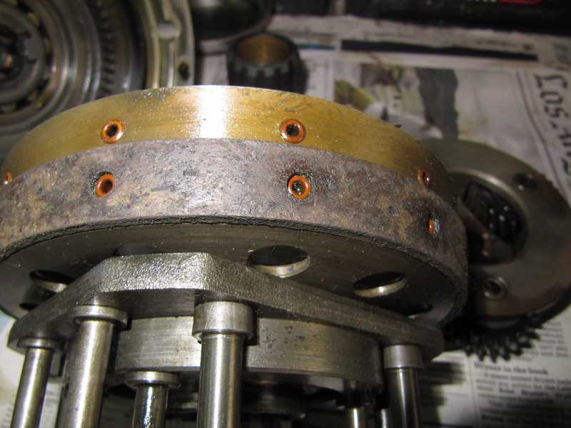
Fortunately, the overdrive clutch, shown below, was in good shape, as you can see plenty of material above the rivets. Its mating surface was also OK. The clutch's friction piece is difficult to find, although there are places that will replace it. Even if you can find the part, it probably requires special tools to rivet it adequately. I simply cleaned and reinstalled it.
The actuator valve and the pump's "antireturn valve" (i.e., check valve) are similar. Their parts must be kept quite clean, and the balls must be scratch-free. The actuator rod has a tiny hole, just below the thick area, which must be kept clear. Any cleanliness problems in those parts could prevent the overdrive from developing adequate pressure or prevent bleed-off of the pressure when turned off. I cleaned everything with fresh solvent and Q-tips; the Q-tips were especially useful for cleaning the long tube for the actuating valve. Just to be sure they were OK, I replaced the 1/4-inch ball in the antireturn valve and the 5/16-inch one in the actuator valve. These are ordinary, high-quality steel ball bearings.
Mating the Transmission and Overdrive
Recognizing that I might have to take the overdrive off the transmission a couple times to get it mated successfully, I put nonhardening sealer on only one side of the overdrive gasket. I expected that rubbery sealer would provide enough flexibility that the side without sealer would conform to its mating surface. I bolted the adapter plate to the overdrive temporarily to compress the gasket while the sealer dried.
(This turned out to be a bad idea. When I reached the point of adding oil to the overdrive, I found a small leak at the lower side of the overdrive-to-transmission interface. When I removed the overdrive, the source of the leak was not obvious; probably, the mating flange on the transmission warped slightly when the lower bolts, which are fairly far apart, were tightened. The new gaskets, also, are much thinner than the old ones, to the point where they are practically useless. If I ever do this again, I'll make my own gasket from soft, 1/16-inch stock. I degreased the surface, installed a new gasket with sealer on both sides, and reinstalled the overdrive. Reinstalling an overdrive is decidedly not fun.
I later learned, to no surprise whatsoever, that this is a common leak point in these transmissions.)
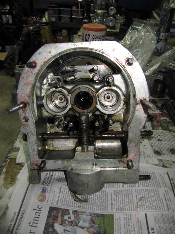
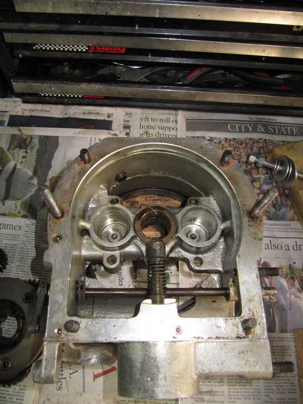
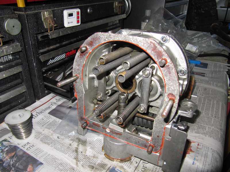
With the accumulator and valves installed, the overdrive was ready to be mated to the transmission. In the figure below, the springs have been installed, probably incorrectly. I didn't realize at first that there are two different kinds of springs, which are very similar, and they must be installed in their correct locations. Fortunately, I figured that out before mounting the overdrive onto the transmission.
A little sealer had exuded into the overdrive's interior. I trimmed it off so it wouldn't come loose, get into the oil, and plug up something important.
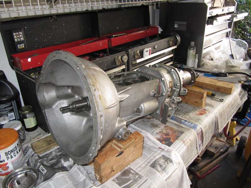
Below, the adapter plate has been installed on the transmission. It was then ready to be mated to the overdrive.
Mating a transmission and overdrive is a little tricky. Eight springs must connect to their mounting points, little nubs on the interface plate, which you can see in the above left picture. The mainshaft must simultaneously engage two sets of splines in the overdrive, and the spring-loaded shaft of the overdrive's pump must be lowered so it fits under the cam. All this must be done while manipulating two rather heavy components.
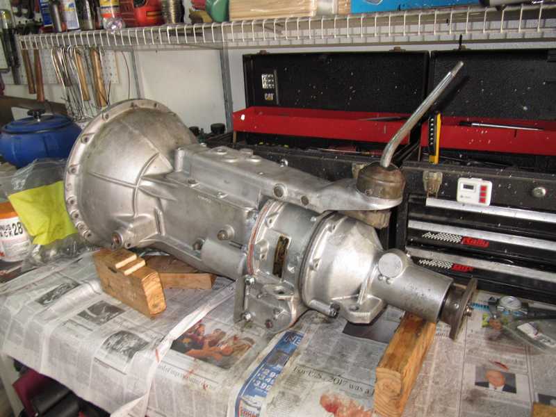
Adding the shifter assembly completed the reassembly of the transmission and overdrive. A couple minor things still needed to be added: the clutch fork and the overdrive solenoid. Those were added after I was sure everything was operating properly.
Testing the Overdrive
An overdrive should be tested before the transmission/overdrive assembly is mounted in the car. Most important are checking the hydraulic pressure and actuator-valve operation.
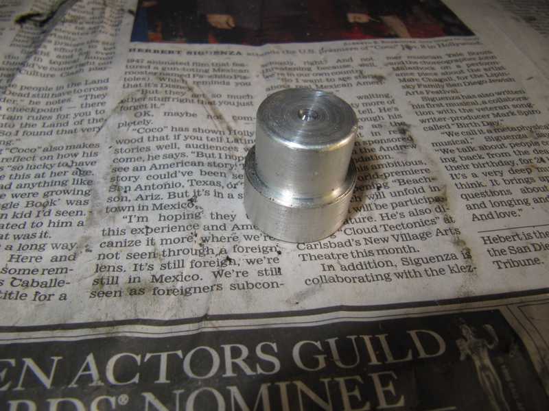
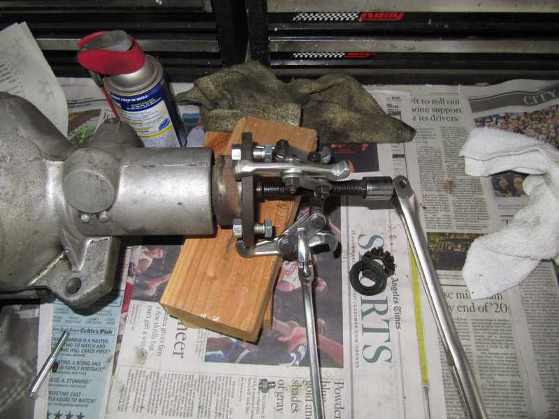
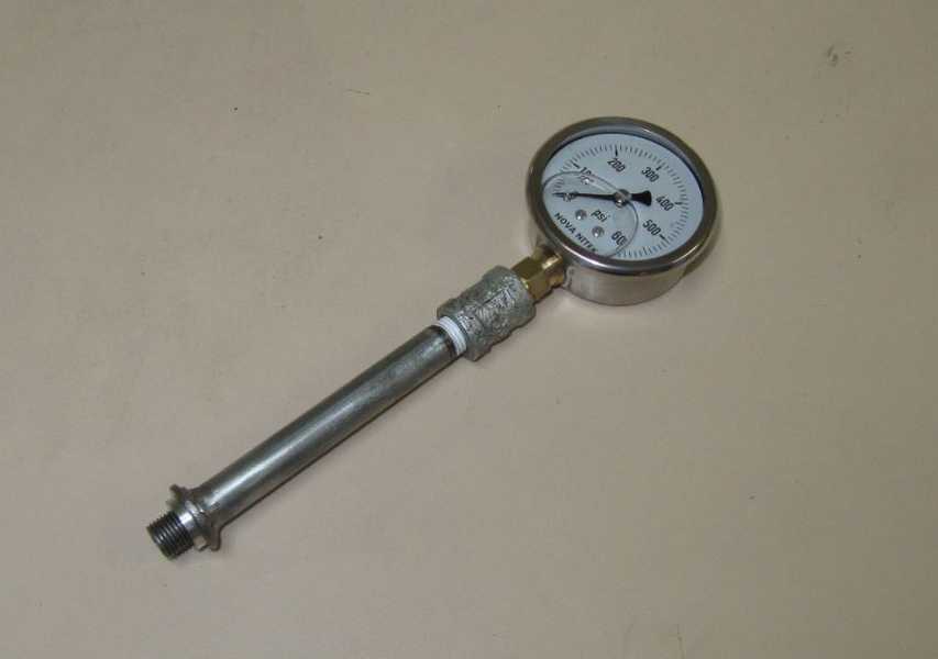
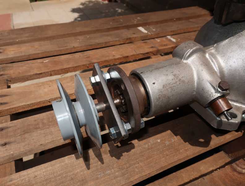
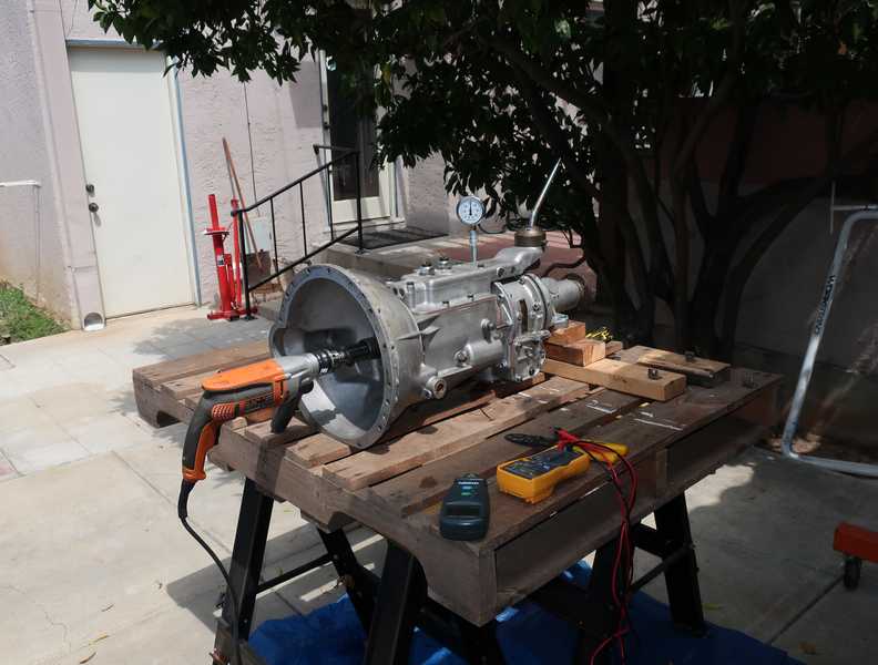
Testing the pressure requires a gauge. It is installed in the actuator-valve port, which has a 1/2-20 (UNF) thread. The gauge is mounted on a piece of steel pipe, which is threaded 1/4" NPT at one end and 1/2-20 at the other. A flange is welded to the pipe. The seal is a thick aluminum washer, which I had to make, as the recess in the overdrive housing is too deep for an ordinary copper washer. I press-fit an orifice into the tube as a stop for the actuator-valve spring. The gauge itself is liquid-filled; the liquid provides additional mechanical damping.
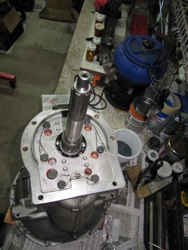
To test the pressure, the overdrive has to be spun up to about 1200 RPM. It's easiest to spin it from the output side. I made an adapter to fit a pulley to the overdrive's output flange; it's just a plate of quarter-inch mild steel with a 1/2-inch rod pressed into it and welded. The pulley slides onto the rod and is held with a pair of setscrews. The pulley also fits the transmission's input shaft, so I have the option of spinning it from the front as well.
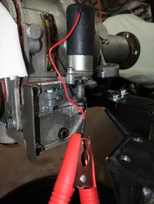
As a first try, I configured the car's generator as a motor, powering it from a car battery and applying a current from a dc power supply to the field coils. That allowed me to use the field current as a speed control. I estimated the generator's power as 1/3 to 1/2 HP; I hoped that would be enough.
I mounted the transmission and generator/motor on a shipping pallet, which was set on a pair of sawhorses. The belt in the picture is the car's ordinary fan belt. To prevent driveway damage from spilled or leaking oil, I placed it all over a plastic tarp. The power supply in the picture below powers only the field coils; a car battery, just out of the picture, powers the motor.
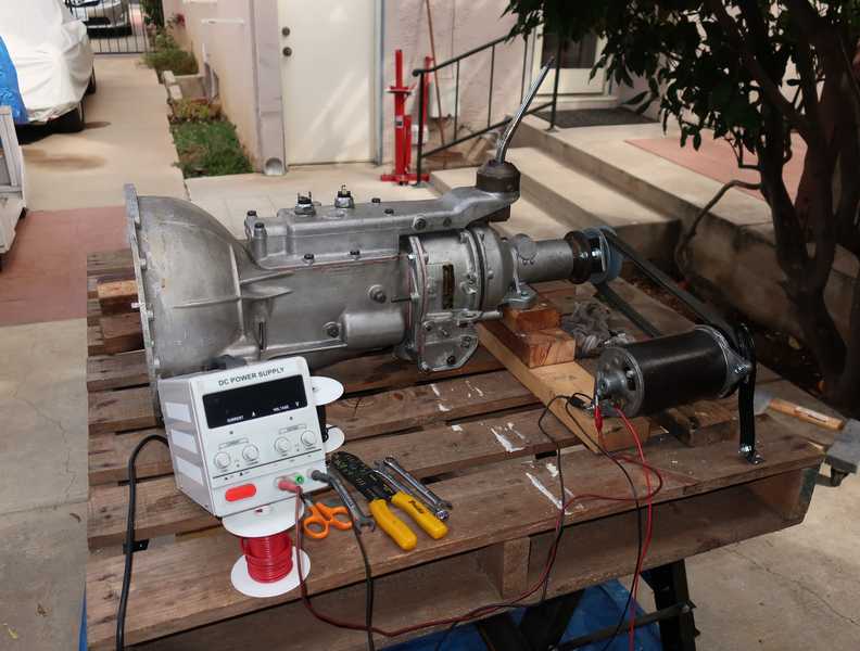
Well, as I often say, the world is full of good ideas that don't work. I couldn't get the speed up to even 400 RPM this way. Instead, just for the helluvit, I tried running the whole thing off my half-inch electric drill. Although the drill is limited to 800 RPM, the pressure came up to 350 PSI; the spec is 360, but that's at 1200 RPM. I could switch the overdrive manually and hear the thing switching in and out. I decided to call that OK, install the solenoid, and do the actuator-valve adjustment.
(As it happened, the overdrive worked just fine.)
Solenoid Installation and Adjustment
Another lesson about the importance of keeping old parts, however grungy and worn out, until the new ones are installed and working.
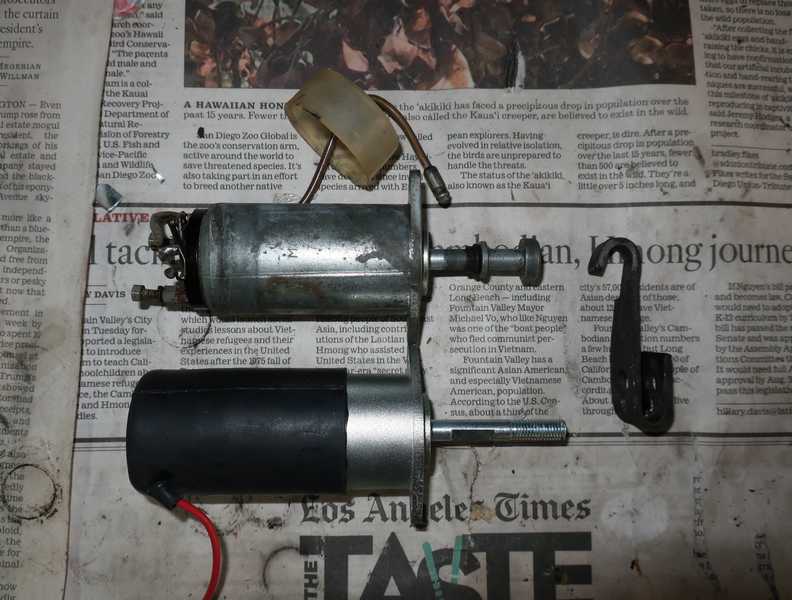
Installing the overdrive solenoid should have been a five-minute, bolt-on job. Instead, it took about an hour. The replacement solenoid simply didn't fit. You can see why: the plunger is about 3/8 inch too long and is very different from the old one. I suspect it was designed to fit a number of different overdrives. If there was room, I could have threaded a nut, locknut, and washer onto the new one, and it would have worked as the old one. Unfortunately, there wasn't room.
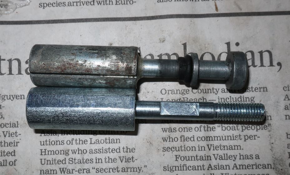
I replaced the new plunger with the old one; it seemed the simplest fix. I then encountered a second problem: a protrusion from the overdrive housing interfered with the larger cover of the new solenoid.
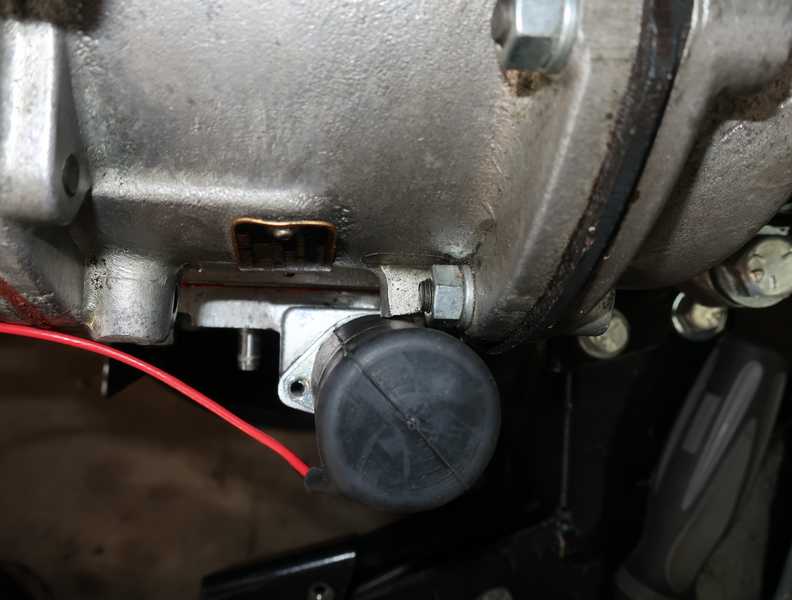
As the protrusion's shape didn't appear to be important, I ground a bit off with a Dremel tool and created enough clearance for the solenoid to fit. When I got the solenoid to sit flat on its mounting surface, I discovered that the locations of the mounting holes in the flange were just a little off, so I had to drill them out fifteen mils or so. Finally, I got the goddam thing into place.
With a little searching, I discovered that correct overdrive solenoids are available from UK suppliers, and, based on catalog sketches (but not photos), some for sale in the US might be correct. I suppose I could have returned the part, but it's entirely likely that the next one I bought would be the same. Better just to deal with it. (Now that I think of it, that probably should be my car-restoration mantra.)
I wasn't prepared to tolerate even slight rust on the plunger, so I galvanized the thick part, which slides inside the solenoid. I didn't care about the rest (which, in any case, was OK), but I was concerned that any further rusting of the upper part could cause it to jam. I also galvanized the actuator lever.
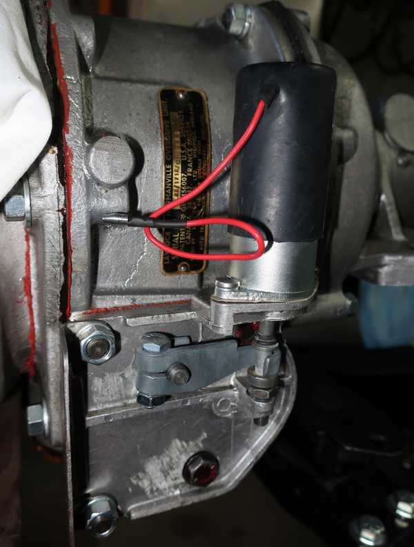
I made a cylindrical aluminum piece to sit on top of the ball in the actuator so I could get a good measurement of its motion. The references at the start of this page discuss the matter endlessly, but all seem to converge to 30 mils as the ideal spec for actuator motion. So, that's what I set it to.
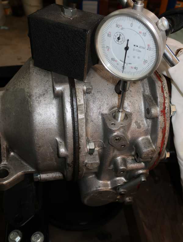
This adjustment is a little tricky, as there is no fluid pressure or spring to return the valve ball to its rest position. I found that the aluminum piece had to be pushed back manually when the solenoid was de-energized, or the measurement was not repeatable.
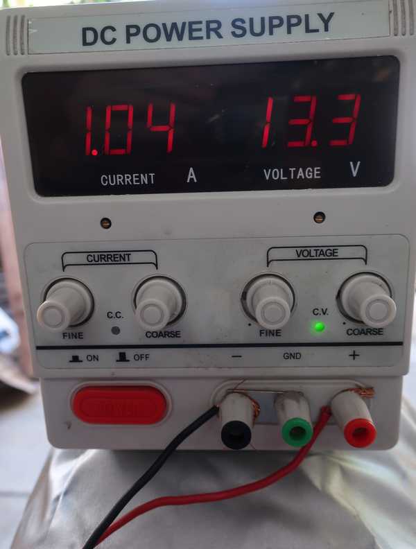
It's always a good idea to check the solenoid current, to verify that the pull-in coil is turning off. Here we see that the solenoid is using only one amp, indicating that the pull-in coil has turned off and only the holding coil is energized. The references make a big deal of this, and I guess it's important. But with a new solenoid, it's hard to see how the test could fail. Something would have to limit the plunger's motion or be jammed pretty badly, and a problem that severe would be obvious.