![]()
Body Electrics
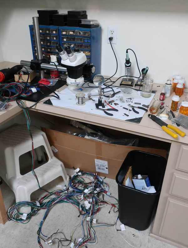
As with other British cars of the era, the electrical system of the Triumph is far from perfect. Its problems include unreliable "bullet" connectors, poor grounds, undersized wiring, failure to use relays where they are warranted, and inadequate fusing. I modified the electrical system to make it safer and more reliable, replacing the bullet connectors with Molex, adding relays for high-current parts of the circuit, and installing additional fusing. As much as possible, I tried to keep appearances original, but reliability and safety were the priorities.
Click on any picture to see a larger version in a new window.
Contents
- Wiring Harness
- Horns
- Voltage Stabilizer
- Headlights, Brake Lights, and Turn Signals
- Windshield Wiper Motor
- Battery Ground
- Voltage Regulator
- Outlet Panel
Wiring Harness
An awful lot of perfectly usable wiring harnesses are replaced every year. Wire does not wear out, and as long as the insulation is not burned, melted, cracking, crumbling, or broken, the harness can be reused. Even if parts of it are damaged, they can be replaced; there are plenty of used harnesses available at throw-away prices, and parts of them can replace any damaged wiring. Solder and heat-shrink tubing are our friends!
That in mind, I chose to restore the existing harness. I reused the wiring but replaced the connectors; the spade connectors were in poor condition, and their replacement was essential. Those crappy bullet connectors, found in all kinds of British cars, are a study in how not to make electrical connectors. I replaced them with with Molex connectors. I depended on chassis grounds only when it made the most sense and used wire returns to a common ground point wherever possible. I replaced the wrapping tape with a woven plastic wrap, which looks a lot like the cloth wraps used in many older cars.
Molex connectors, if you are not familiar with them, are the nylon multipin connectors you may have seen in your computer. They are available in a number of sizes. I chose the 0.093" diameter pins, as they are good for 14 amps (a little lower if a connector has a large number of pins) and their relatively large size is not a problem. The next smaller size, 0.062", is good for 5 amps, which is marginal for some circuits. I bought a number of 1- through 4-pin connectors; I could not conceive of any situation where I would need a larger pin count. These connectors are not waterproof (neither are the original bullet connectors, for that matter), but they are located in reasonably well protected areas, so that shouldn't be a problem.
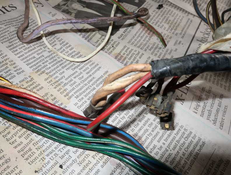
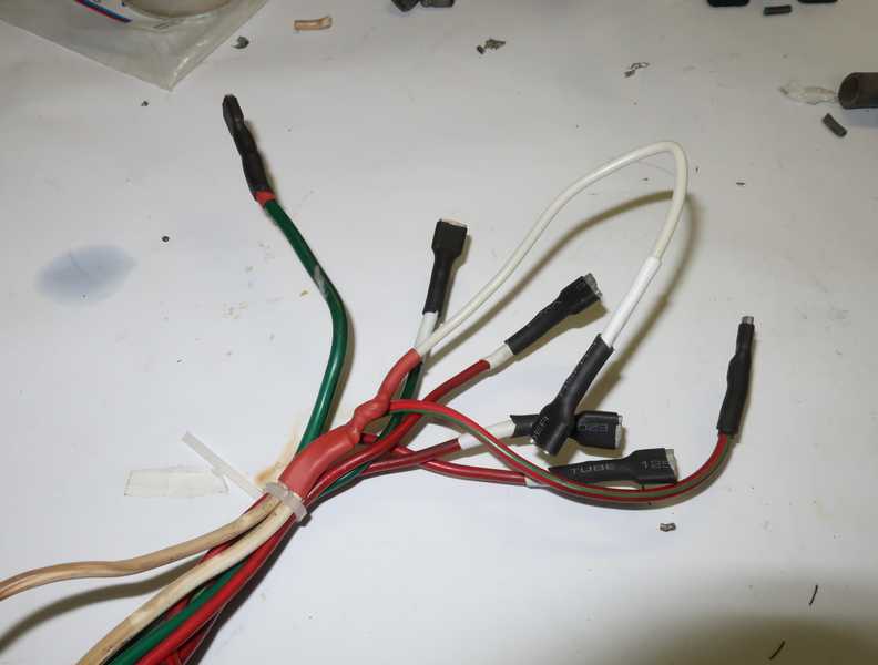
Below, the connections from the fuse block. The white wires had damaged insulation, probably melted by high current. Virtually all of the spade connectors were as corroded as those in the picture; all had to be replaced.
The first task was to get the old wrapping tape off the harness. Fortunately, the original wrap was an adhesive-free tape, which was bonded only at the ends of each wrapped section. It was easy to remove and didn't leave the wires gunky. Occasionally, especially at break-out points, the wires were first wrapped with cloth electrical tape, a gooey, disgusting product I haven't seen in the wild since about 1970, and I don't lament its extinction. I cut it off and, fortunately, the remaining gunk was easily removed by denatured alcohol.
As I unwrapped and cleaned the harness, I tied it with small zip ties. The insulation under the wrap had not deteriorated at all; it was as flexible as new wire and its colors were bright. Outside of the wrap, though, some areas needed a little help.
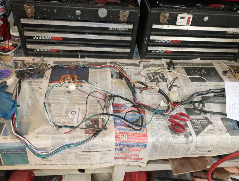
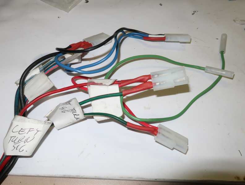
With the help of a wiring diagram, I then went through the harness and marked the connections with paper labels. Many of the exposed wires' colors had faded, so it was sometimes tricky to figure out the purpose of some connections. I traced wires through the harness (not difficult with the wrapping removed), and used an ohmmeter to verify them.
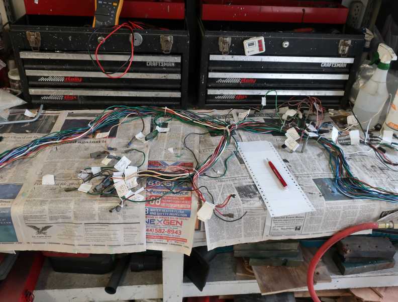
All of the connectors had to be replaced. Working with the harness was a chaotic business, but labels and written plans helped a lot.
I replaced the spade connectors with new, soldered ones and insulated them with heat-shrink tubing. Because the copper tarnishes, soldering old wiring can be difficult. It can be cleaned easily by fanning out the strands and dipping them into a weak acid, taking care to minimize wicking of the acid up under the insulation. Once the copper is bright, the acid should be neutralized by dipping the wire end into an alkali solution. I used very dilute hydrochloric acid for cleaning the copper; something as simple as lemon juice might be enough. A solution of baking soda, washing soda, or ammonia is fine for neutralizing the acid.
The left picture, below, shows the restored connections for the fuse block; the original terminals are shown in the first picture of this section. The Molex connectors at the harness' headlight breakout are shown in the right picture, below. I left the tags in place until I was sure everything was working. (The connections in the left picture are also tagged, but the tags are out of the picture.)
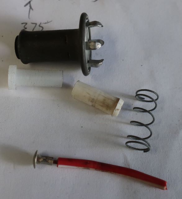
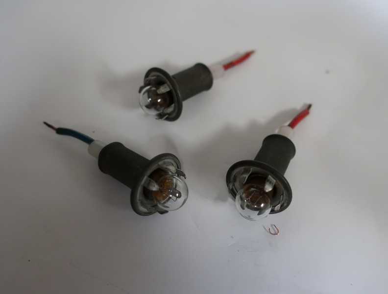
The harness included three lamps that clipped into the speedometer and tachometer, two for illumination and one for the high-beam indicator. All three appeared to use an odd, cylindrical connector. I didn't think much about them, figuring that I'd see how they worked when I installed the lamps. It turned out that the "connectors" were the broken internal insulators of the lamp holders; I had to make new ones from stock nylon rod. The pictures below show the lamps, along with both the old and new insulators.
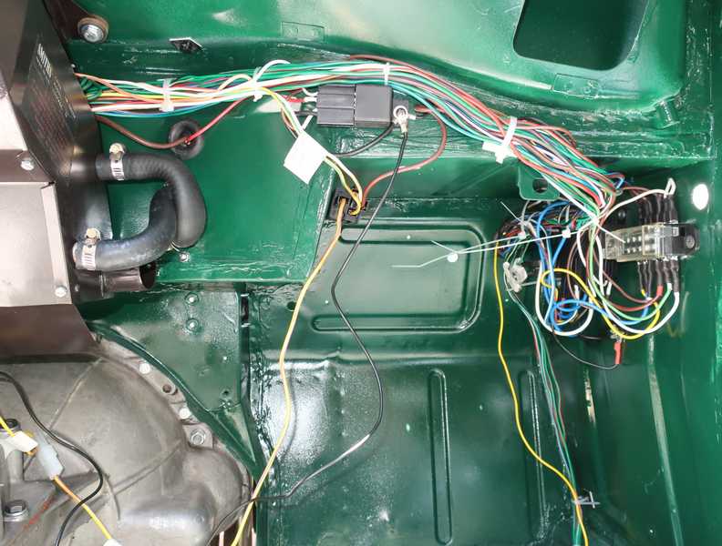
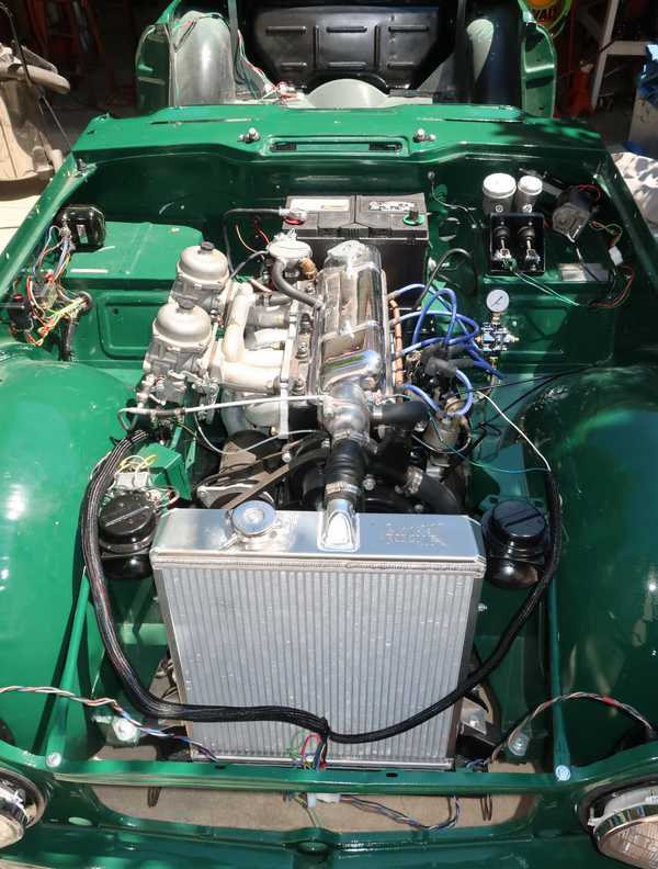
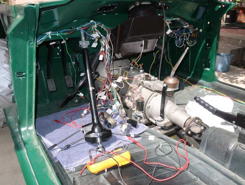
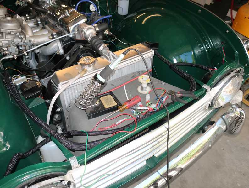
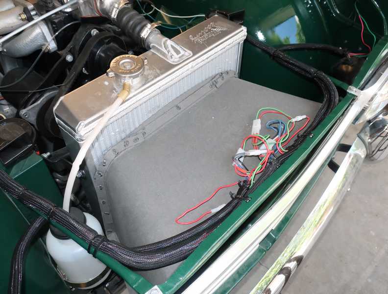
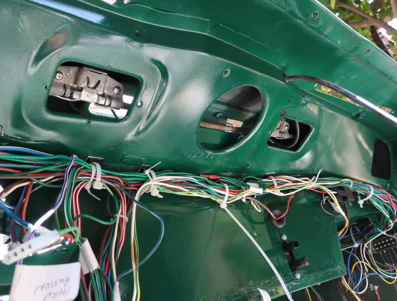
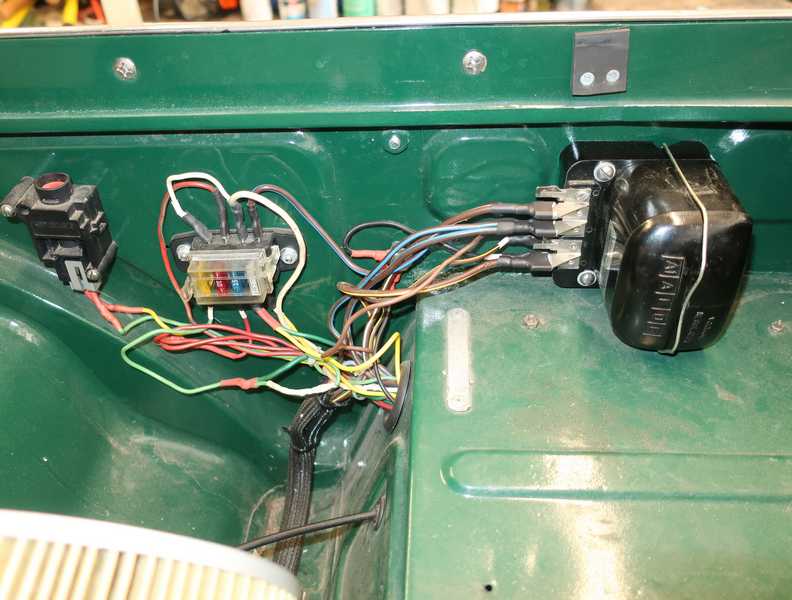
Initially, the wiring harness was installed unwrapped, as it was necessary to add additional wiring for relays and more extensive fusing, and it was difficult to determine exactly where the breakouts would be. In the picture below, the new fuse block and relays are mounted near the top of the passenger footwell. The relays on the right are for the headlights and switched power (i.e., power that is turned on and off by the ignition switch); the one on the left is the overdrive relay. The one most easily visible, at the top left, is for the starting solenoid. It's a relay that operates a relay, which at first may seem odd. In fact, the starting solenoid pulls something north of 5 amps, so it can erode the ignition switch's contacts significantly. The relay extends the life of the switch by preventing that. (Eventually, I had to move this relay, as it interfered with the back of the glove box.)
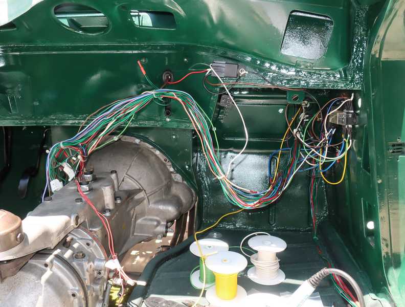
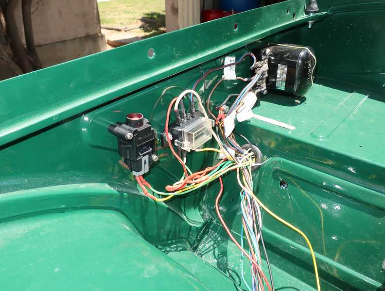
For improved reliability, the original cartridge-fuse block was replaced by a more modern one, which used ATC fuses. It also allowed me to move the horn fuse to the block; originally, it used an in-line fuse holder, which looked like an afterthought. The item to its left is an impact switch, which shuts off the electric fuel pump in the event of an accident. The chassis ground near the voltage regulator serves as a common-ground point. Except for a couple places where it really didn't matter, or was impractical to do otherwise, I avoided using local, chassis grounds.
In these pictures, the wiring looks like complete chaos, but it's actually well organized. At this point, though, it's unavoidably messy .
I didn't wrap the part of the harness behind the dash, as it really wasn't necessary, and with wires emerging from it at multiple points, wrapping would have been difficult. The original wiring supports were removed to make the body easier to strip and repaint, so I first tried supporting the harness with cable ties and stick-on mounts. To prevent the weight of the cables from pulling the mounts off, I used quite a few. That didn't work, however, so I replaced them by mounts that could be screwed to the body.
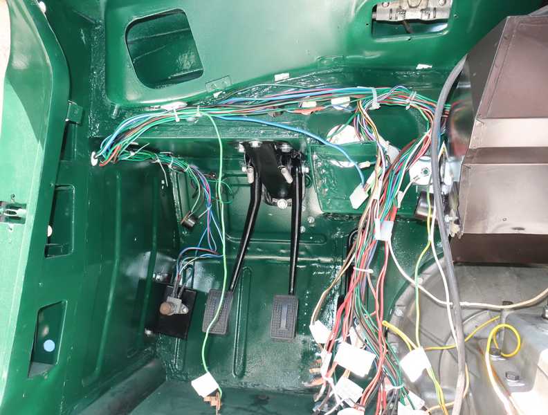
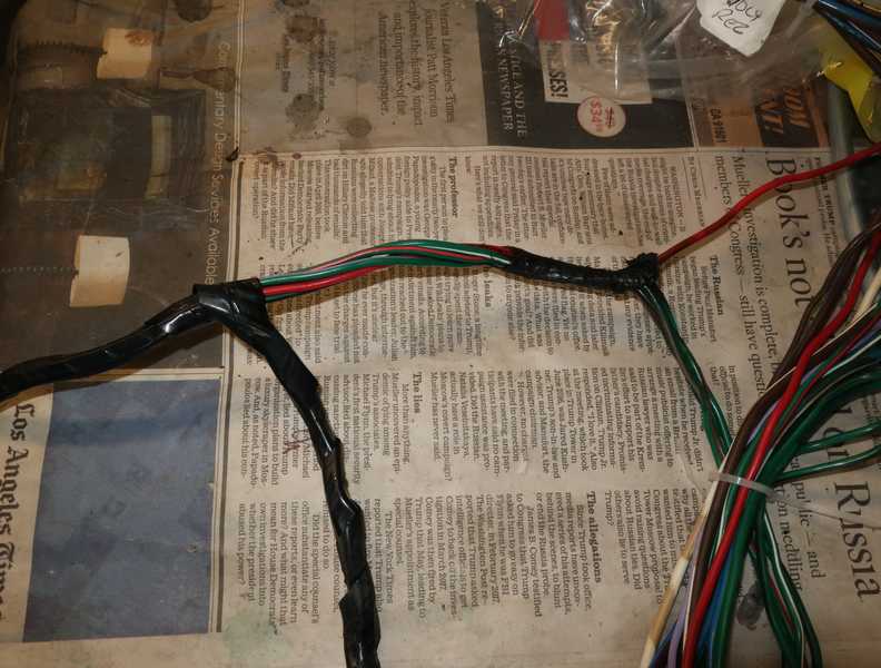
The wiring elsewhere was wrapped in a woven plastic cable covering. If you don't examine it carefully, it looks like a period material.
Here is the finished front breakout. At this point, all the front and side lights and their cable coverings were installed.

It's important to test the wiring before installing the dashboard, as fixing something with the dash in place could be difficult. I hooked up the switches and meters temporarily. At first, I powered everything from a dc power supply that was current-limited to 10 amps, so a short circuit would not damage the wiring. I checked as much as I could this way; then, to test high-current items, like the headlights, I connected the battery.
The tail-light bodies could not be installed because they still needed plating. I connected the sockets to the tail-light wiring so I could check their operation.
I found only one mistake: a miswired connector at the steering column. It was easily corrected, but it would have been a pain to fix after the dashboard was in place. I'm glad I took the time to test it all.
Horns
The TR4A horns are not unlike the horns on other cars, even today. The car has two horns, high- and low-pitched ones, giving the sound a louder but more melodic tone than only one could provide.
I tested the horns before restoring them, then cleaned and painted them, and put them into storage. A couple years later, I installed them on the car.
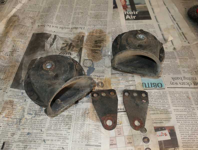
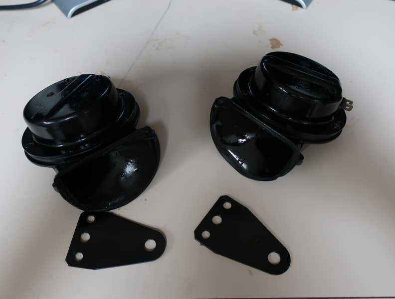
When I tested the electrical system, I discovered that one horn had stopped working. Rather than spend a lot of time fixing it, I bought a pair of Hella universal-replacement horns. They are not identical to the TR horns, but they look right and are much louder.
The original horn fuse was in an in-line holder near the fuse block. To me, it seemed like an afterthought (which it may well have been), so I relocated it into the new fuse block. It is a 20-amp fuse, as these horns use more current than the originals.
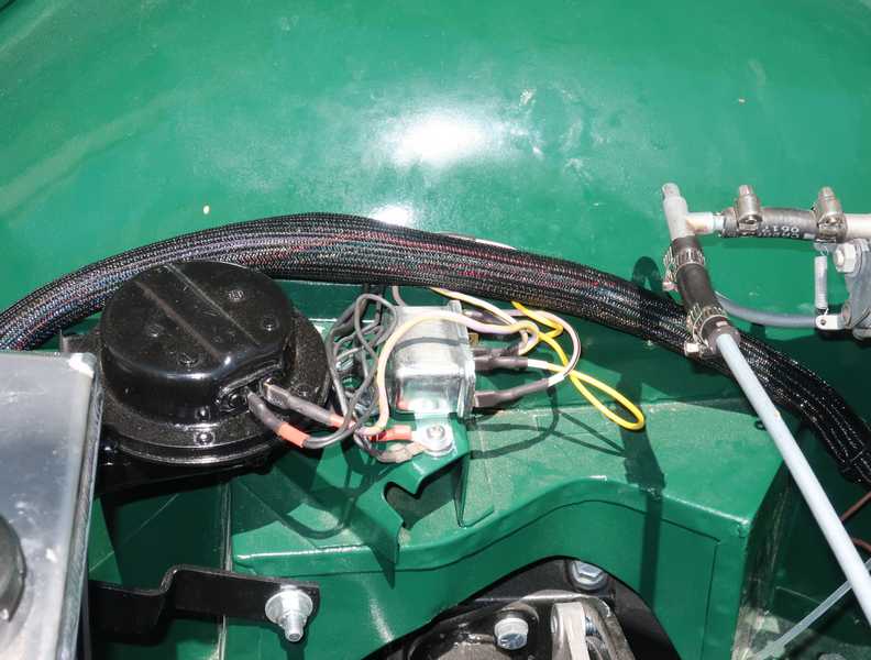
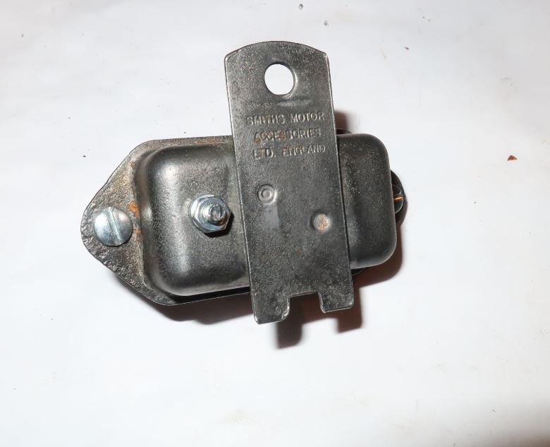
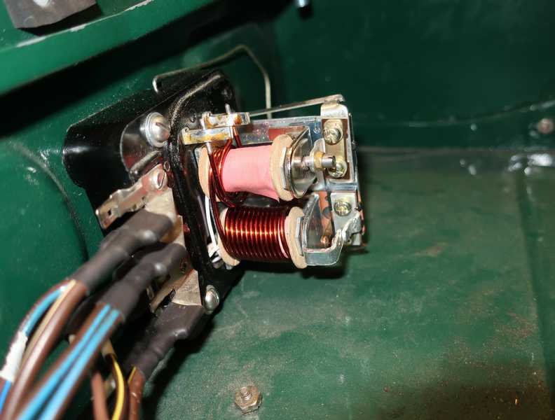
Voltage Stabilizer
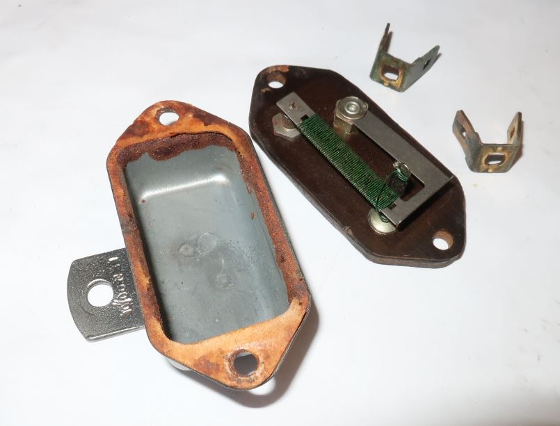
The original voltage stabilizer, which provides 10V to the fuel and temperature gauges, is a thermal device. It uses a resistance-wire heater and a bimetallic strip, which rapidly interrupts the current to the gauges, creating (we can hope...) the desired average output voltage. I guess it works.
Today we have voltage-regulator ICs that provide a rock-solid output voltage over wide variations in input voltage and output current. One choice is the widely available 7810 IC, having an output voltage of 10V. Many automotive electrogeeks do not recommend it, as its dropout (the minimum voltage between input and output) is a little over 2V, which they view as marginal. Instead, they recommend a "low-dropout" regulator, which has a dropout around 1V. This isn't a critical application, however, so I think the 7810 actually would be fine. If the output dropped a little below 10V on occasion, I don't think you'd ever notice it; the temperature and fuel gauges that it powers are not precision instruments.
In any case, I used an LT1086 "low-dropout" regulator, which has a dropout around 1V at the current used by the gauges. I mounted it, along with necessary capacitors and resistors, in the enclosure that held the thermal regulator. A few dabs of epoxy prevented the parts from moving and creating a short circuit. I also wrapped mylar tape around the inside walls of the metal cover.
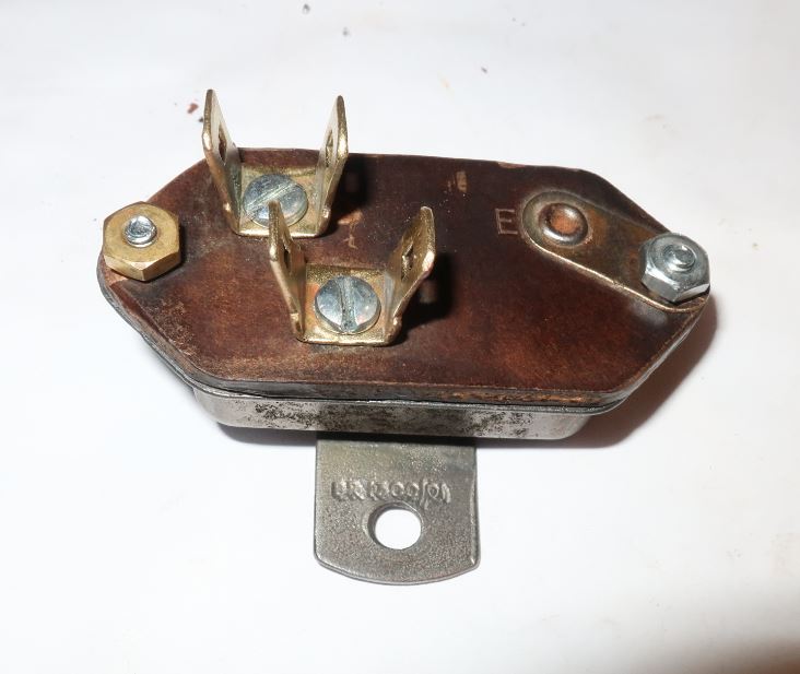
The IC may dissipate a fair amount of heat, as the gauges can draw a couple hundred mA. To provide a little heat sinking, I mounted the LT1086 on the inside of the cover. The IC's mounting tab, which is connected to the output, had to be insulated from the metal; insulated mounting hardware is readily available.
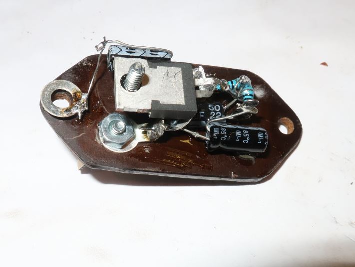
After all that, when I tested the electrics, I found that the regulator chip was blown. Screw it; I replaced it with a 7809 (9V) with a diode in series with its ground lead, as I didn't have a 7810 (10V). That gave a solid 9.7V output; close enough. Also, the 7809 didn't need so many ancillary components, and its mounting tab was ground, so it didn't need the insulator.
Headlights, Brake Lights, and Turn Signals
Headlights
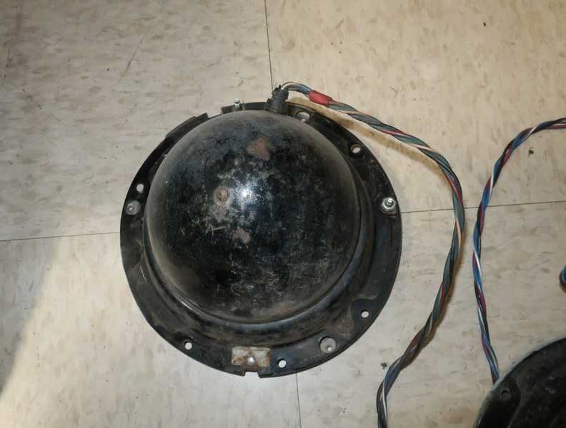
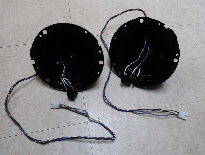
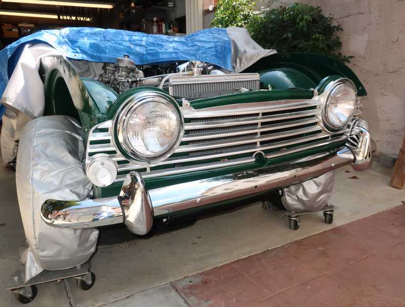
The headlight buckets were a little beat up, but otherwise not in bad shape. A bit of a surprise for a car that clearly had been whacked in the front a couple times.
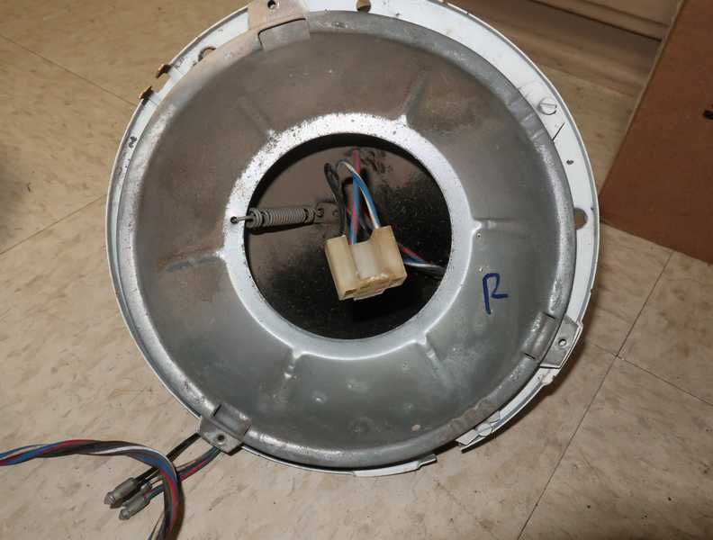
That galvanized bowl-shaped piece was fine for reuse, but I replaced the support springs; the existing ones appeared to be too-stiff replacements.
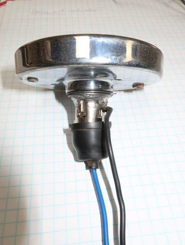
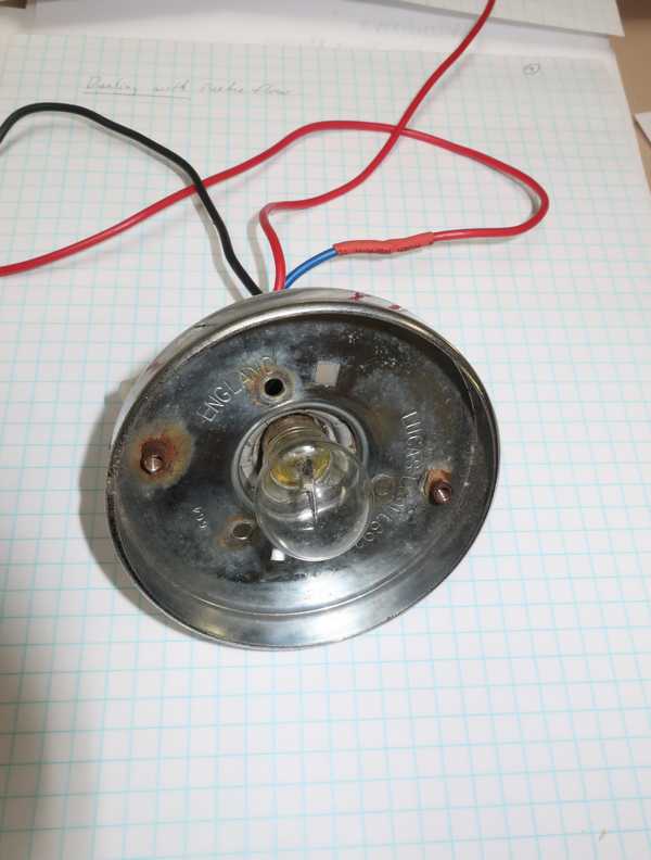
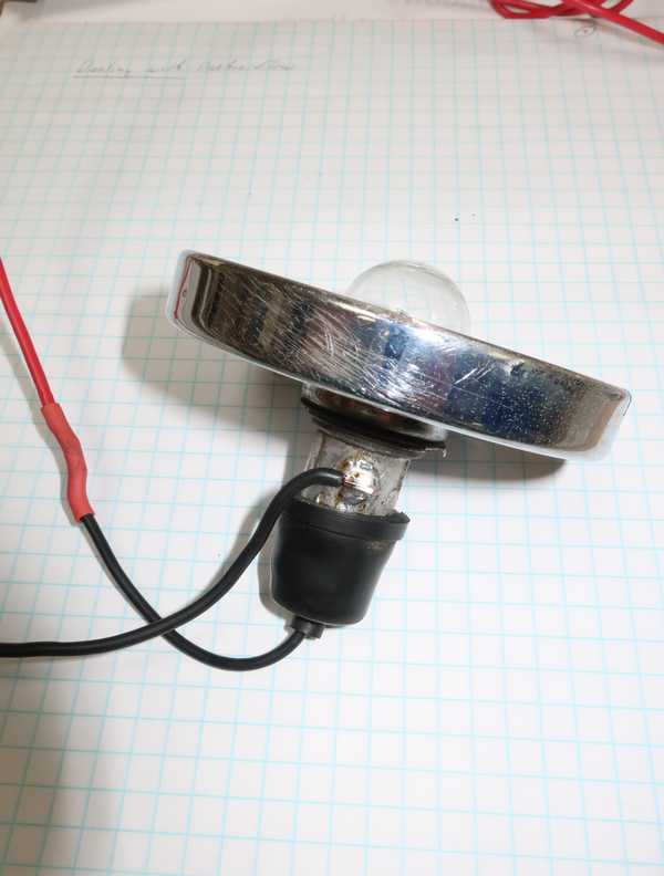
Cleaning and repainting the headlight "buckets" was straightforward. I replaced the headlight connectors (the buckets still had the original Lucas ones) and, of course, replaced the bullets with Molex connectors.
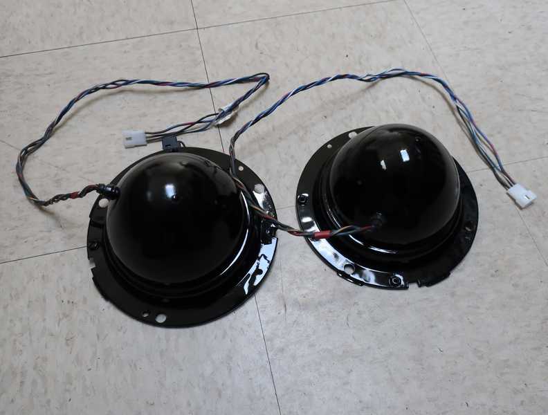
The headlights required a kind of captured nut that fit into a 3/8-inch square opening in the body. The original ones were too rusted to reuse, but McMaster-Carr had acceptable substitutes. Assembly was straightforward; everything was keyed or fit only one way, so the lights couldn't be assembled incorrectly.
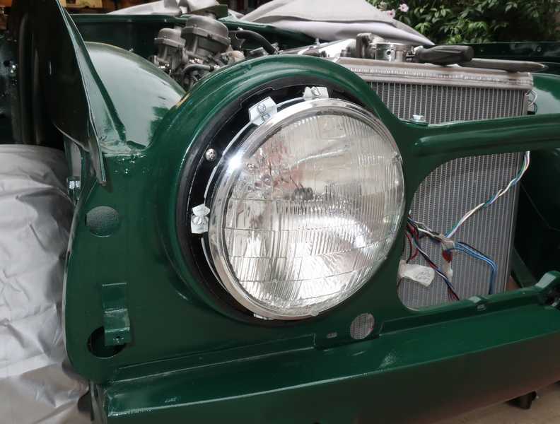
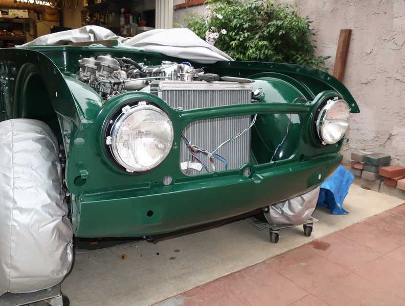
I adjusted the headlights at night by the position of the main beams. They should be aimed slightly to the right of the car's center line and illuminate the road close enough so that the road surface is easily visible, but you can still see reasonably far ahead. I checked them by driving the car at night, stopping occasionally, and tweaking the adjustments.
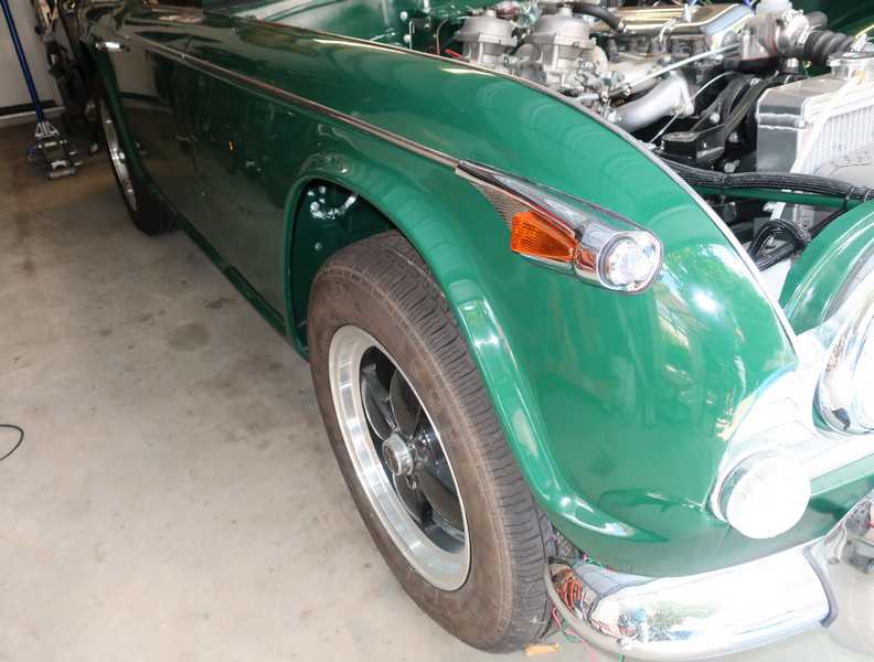
Front Turn Signals
The turn signals were restorable. On one side, the socket was OK, but the other was too rusted to use. On that side, I cut off the old socket shell and soldered on a new one. The bulb now protrudes about 1/8 inch more that it did originally, but there is plenty of space under the lens, so that shouldn't matter.
Of course, I soldered the ground connections to eliminate that stupid bullet connector.
Below, the second one. I replaced the socket internals but kept the shell.
Below, the turn signals mounted on the grille.
Tail and License-Plate Lights
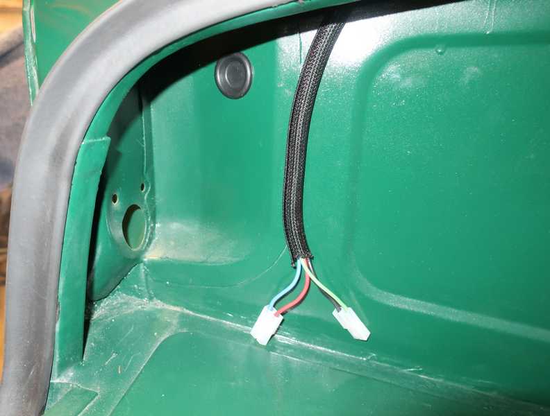
I had started to restore the original tail lights, with new sockets and such, but I got some bad news when I tried to get the tail-light bodies plated. The plater could not guarantee a good job, as they were too pitted. Reluctantly I bought a pair of replacement lights and installed Molex connectors onto the lights and harness ends. They could not be installed until the rear fenders were mounted, as they fit overtop of the fender edge.
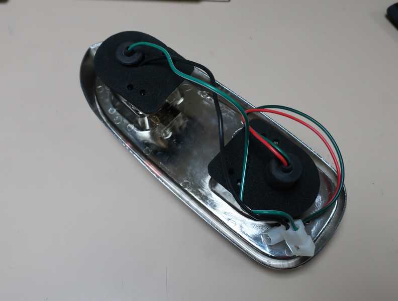
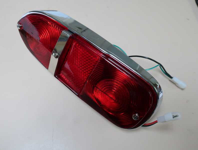
I had less than the average amount of trouble with them: the mounting screws were not included, so I had to buy something acceptable; it was necessary to chase the holes for the lens-mounting screws; and one bulb wouldn't fit into its socket. Since the bulb couldn't be installed, the assembler kindly left it loose in the lamp compartment. That was thoughtful. I also discovered, the hard way, of course, that the lens cracks easily if you don't tighten its screws with excruciating care. Best to tighten them in stages, first the top and bottom ones, then the center one.
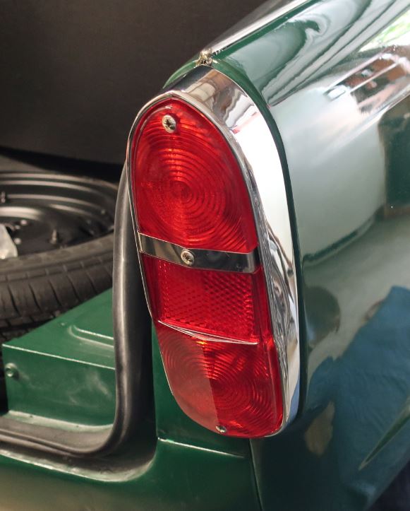
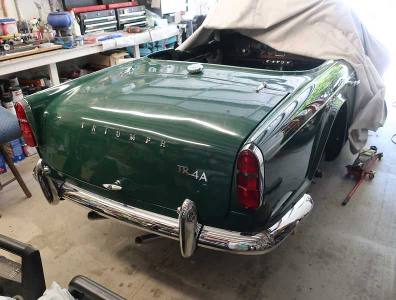
Anyway, the fenders eventually were finished and, with some difficulty, mounted. Here is the mounted tail light.
The license-plate lights are located in the rear bumper overriders, which I had replated. I bought new light assemblies, but they didn't fit well; typical.
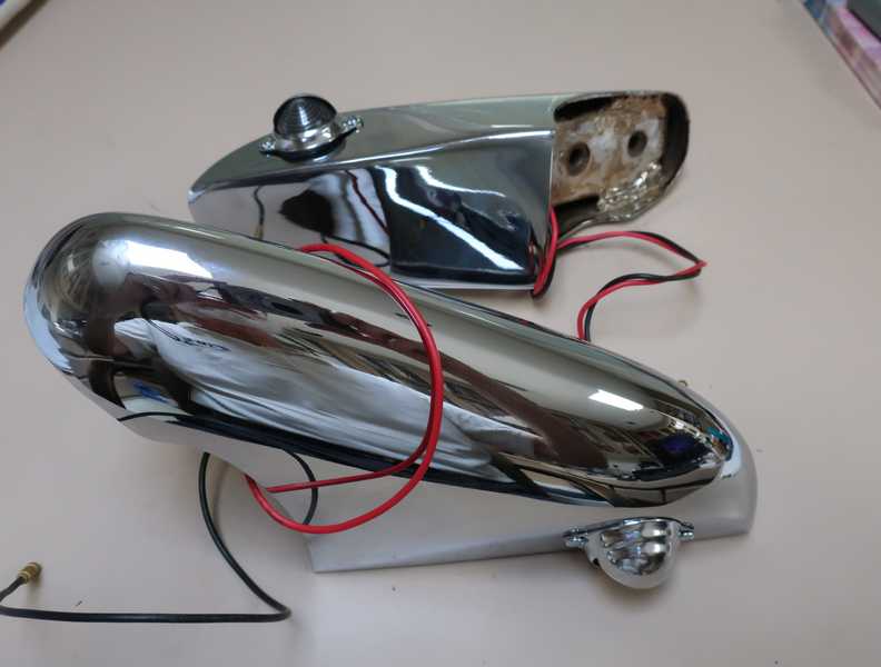
Below, the finished rear end, with bumpers and all lights in place.
Front Sidelights/Turn-Signal Repeaters
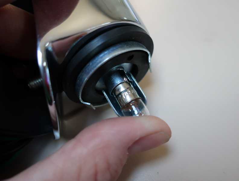
Similarly, I had to buy new front sidelights. One was OK, but the other came with a cracked lens. Fortunately, I had a spare, which I bought when I expected to restore the original light. Additionally, because of burrs on the socket, the bulb under the front lens couldn't be inserted. I filed the burrs off with a small, rat-tail file, and the bulb fit acceptably.
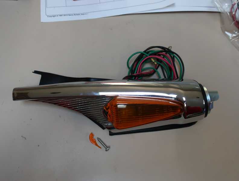
I paid a bit over $700 for these four lamps, shipped from the UK. For that, I should not have experienced these problems.
I installed Molex connectors on the lamp wiring, connected them to the breakout above the radiator, and tested the lamps. The breakout looks a little messy, but it's no worse than the original wiring.
Below, an installed lamp assembly. The lamp with the amber lens is the turn-signal repeater; the clear one is the sidelight.
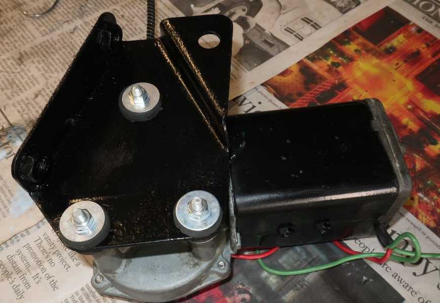
Windshield Wiper Motor
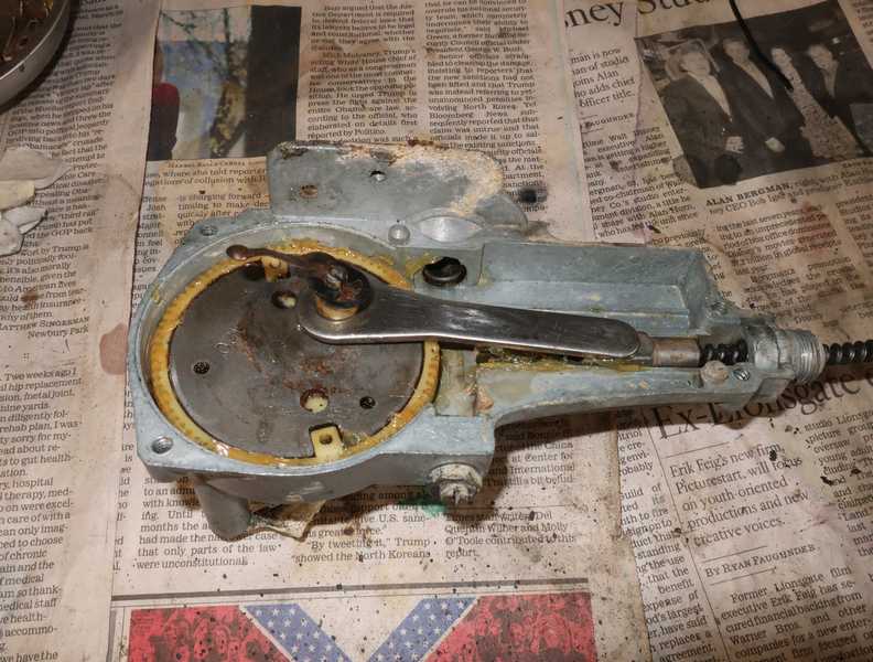
The wiper motor was pretty grim. It would have been easy to justify replacing it, but finding a new one these days is complicated. Direct replacements seem to be unavailable in the US, but later units (TR6, I think) are available and can be adapted to fit. Acceptable replacements, if they can be found, cost at least a couple hundred bucks plus, perhaps, shipping from the UK. The best option was to restore the old motor.
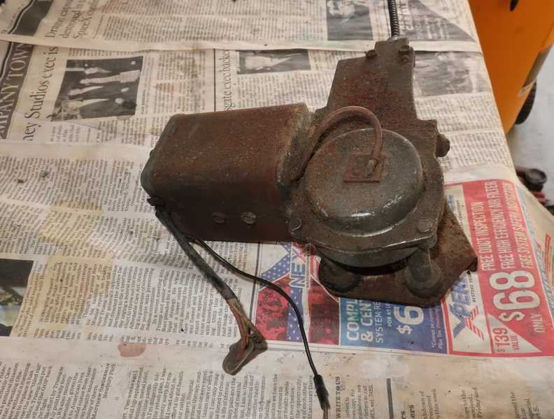
The whole contraption is held together by two long screws going all the way through the motor's body. The latter is a thick piece of steel, which acts as a pole piece for the motor. Remove the screws, and the whole thing falls apart. Then, removing the gearbox cover allows access to the rest of the mechanical stuff.
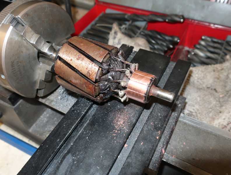
On disassembly, the wiper motor appeared similar to those of other 60s-era cars: a small motor and a worm gear plus a crank, the latter potted in grease, which long ago had dried out and hardened. The brushes were worn down to the holders; I doubt that they had ever been replaced. The commutator was moderately worn. The motor was not the worst I've seen, but it certainly was due for some work.
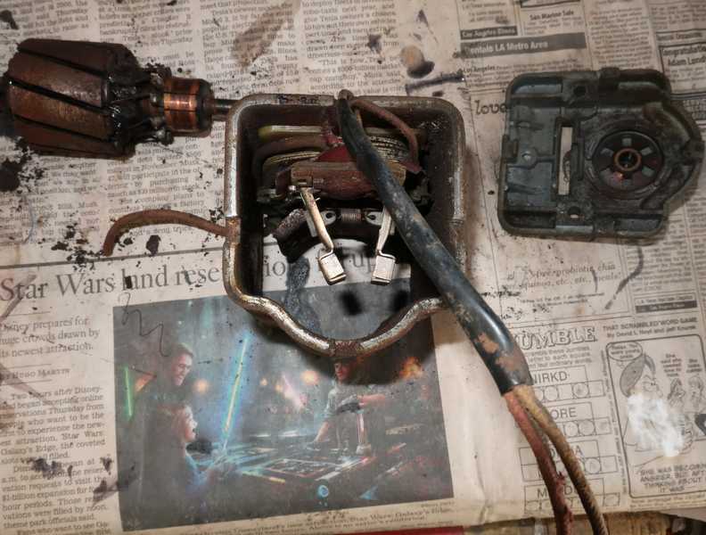
Disassembling the motor required quite a bit of care. A few small, hard-to-replace parts were held in position by the armature, and when it was removed, they simply fell out. Similarly, the large gear and sliding contact were held in place by special snap rings, which probably could not be replaced by generic ones.
I cleaned up the armature and polished the commutator a bit, leaving some swarf in the gaps between the commutator segments. I cleaned it with carb cleaner and an air hose. (I later learned that it's common for these motors to have seriously uneven commutator wear; this one's wear was comparatively mild.)
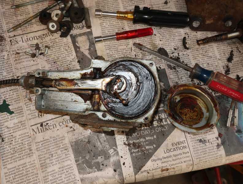
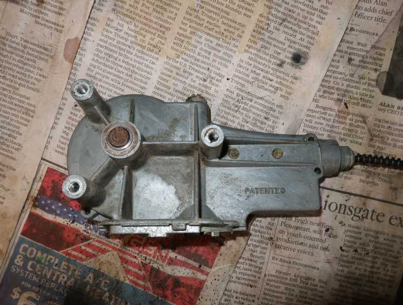
I cleaned and wire-brushed the outer parts, painted them with rust converter, and finally applied black paint. The gearbox cover was originally galvanized; I could have replated it but instead decided, for simplicity, just to paint the outer surface.
The gears and other internals also were cleaned, relubricated, and reassembled. The output cable had been packed with grease, which had hardened, so it likewise was cleaned. The gears probably should have more grease than is visible in the pictures, but I think that the huge amount often used is excessive.
I reassembled the motor with new brushes and tested it before installing the gear cover. It ran fine, both speeds working.
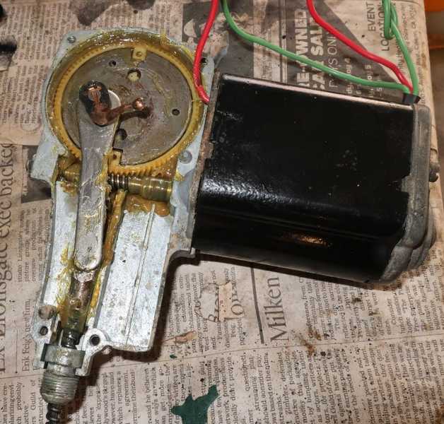
I finished the assembly, installed the mounting bracket with new hardware, and ran it one more time to be sure all was well.
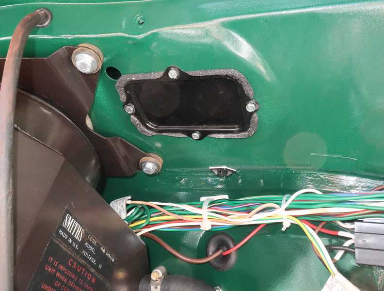
The wipers' parking position is adjusted by turning the cylindrical cap. Loosening the cover-plate screws allows it to move; then, with the cable in its maximum extended position, the cover is turned in a counter-clockwise direction until an ohmmeter indicates an open circuit to ground at the cap's electrical connection.
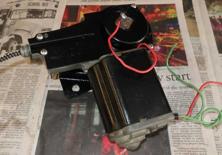
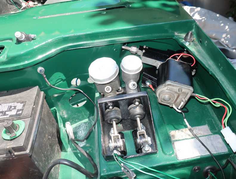
Below, the motor, installed.
The wiper mechanism. It's important to get it right, as it's a supreme bitch to work on, once the dashboard is installed. I tested the wiper motor and drive mechanism when I checked the electrics; it ran smoothly, both speeds.
I used black rubber tubing for the windshield washers, not the usual clear vinyl, as that was what I had. Since the washer pump that came with the car was broken, I used a syringe filled with water to test the washers. The water flowed nicely, and they produced a good stream.
Once I was sure that everything was working, I installed the access covers with home-made foam gaskets.
Battery Ground
I never liked the practice of grounding the battery directly to the body. The body is made of thin steel, and steel is not a great conductor. Then, the high starting current must find its way through the body to the frame and then through a ground strap to the engine block. It doesn't make much sense to run high starting current through a long, haphazard path like this. I'd be willing to bet that one to two volts are lost between the battery and starter.
I think it makes more sense to ground the battery to the engine block, so I connected the battery ground to one of the former fuel-pump mounting bolts. (I replaced the mechanical fuel pump with an electrical one; look here for more info.) I then ran a braided strap from the block to the frame and a separate low-current wire from the battery to the body. The latter is a compromise; I would have preferred to daisy-chain the braided wire from the block to the frame to the body, but there was no good location on the body for it. The picture below shows these connections.
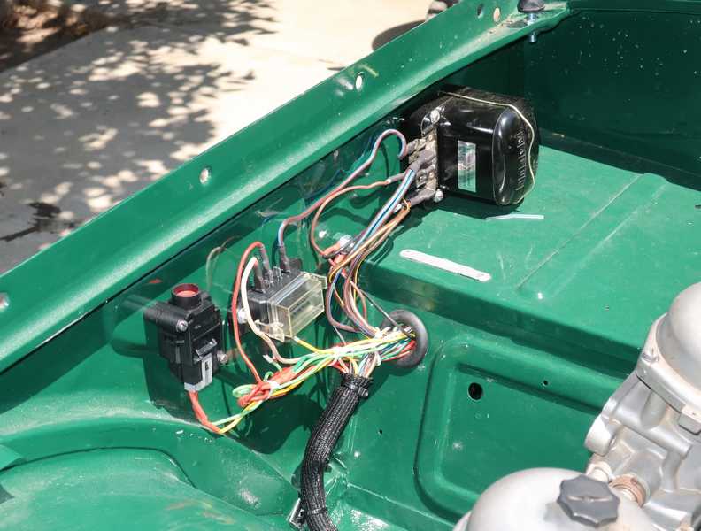
Voltage Regulator
It's astonishing how one simple part can suck up a disproportionate amount of time, attention, energy, and (of course) money. That was the case with my voltage regulator. I started by using off-the-shelf Lucas parts (will I never learn?) in order to avoid having to design my own regulator, and ended up designing my own regulator. Sigh.
Adjusting the Electromechanical Regulator
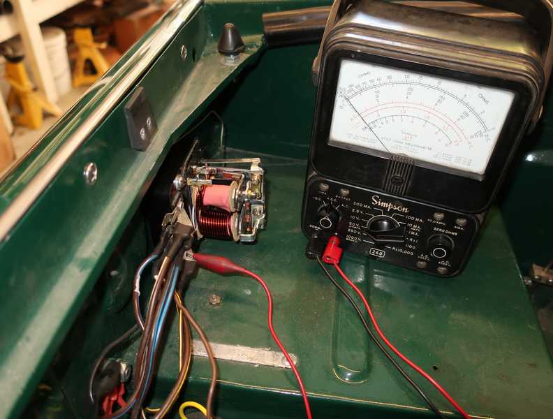
After driving the car with a temporary voltmeter connected, it became clear that the charging system was not working right. The problem turned out to be my new Lucas voltage regulator, which was not adjusted right at the factory.
When I removed the regulator's cover, I first noticed that the cutout contacts were not closing and the generator's output was only about 12V. There clearly was a problem, so I removed the box and checked it on the bench, where I could connect an adjustable dc power supply and an accurate, digital meter. I discovered that the cutout contacts closed at 14.5V, much greater than the specified 12.7 to 13.3V. Worse, the contacts did not close sharply; instead, as I increased the voltage, the armature hovered a bit and slowly nestled into position. That behavior proved that the basic mechanical adjustment was not right, as well.
I went through the shop-manual procedure for adjusting the cutout. Rather than adhere slavishly to all the specified dimensions, I made sure that the relay armature closed crisply, with a satisfying snap, when the correct voltage was reached. That's really all that mattered.
Next, I determined that the regulator relay had the same problem. I readjusted it as well, both electrically and mechanically. The manual tells us first to set the gap between the armature and the core, then adjust the contacts so they are just barely closed when the relay is not energized. That doesn't work. There has to be a little pressure on the contacts, or they simply do not conduct, and that pressure inevitably changes the armature gap. Again, with a little finagling of all the adjustments, it closed as it should. I set the voltage initially to 16V, planning to fine-tune it on the car.
In adjusting the regulator voltage, the shop manual tells us to put a piece of cardboard between the cutout contacts. That disconnects the generator from the car's electrics, allowing it to be adjusted without a load. However, it still allows current from the battery in the coarse winding of the regulator coil, which could affect the adjustment. Perhaps that is a minor effect, but I think it would be better to adjust the box with the A and A1 connections removed and tied together. That would unload the generator and zero the current in the regulator coil; it is also what Lucas recommends in their literature from the 1960s.
The adjustment is a little touchy. Per the shop manual and other references, I set it to 16.0V at a temperature of ~30C. Because of voltage spikes, it is necessary to use a moving-coil voltmeter or a digital one with appropriate RC filtering. I used my venerable Simpson 260 meter for the adjustment, but a filtered digital meter might be easier to read and would be more accurate.
Once it was adjusted correctly, the regulator kept the battery voltage above 13.5V in normal driving, although with quite a bit more variability than I had expected. Oddly, after driving the car for a couple hours, the system voltage dropped below 13V and stayed there. I wasn't happy with that, as it is probably caused by misdesigned temperature compensation. But that seems to be how they work. The alternative is an electronic regulator.
Electronic Regulator
Although I have a number of circuit plans for electronic regulators, I simply was not in the mood to build one. Instead, I bought a Lucas electronic regulator. I have encountered this model from time to time but never used it on any of my own cars. It is advertised as a "digital" regulator, but I doubt that there are any digital circuits in it. It came from British Parts Northwest and cost about $80 USD. It is visually identical to the electromechanical regulator.
The build quality of this regulator is execrable. The electronics board is mounted, more or less, on an aluminum heat sink by cross-threaded screws. It is not mounted on standoff insulators, so there is nothing to keep the board away from the heat sink, and the wiring can short-circuit to it. The heat sink is pointless, anyway, because it is inside the regulator enclosure, so there is no possibility of air circulation around it. The unit is available only with screw connections.
I remounted the board as best I could, but it still wasn't straight. The wires at the bottom were very stiff, probably no. 12, making the board difficult to reorient.
The board has two potentiometer adjustments. No information was included with the regulator, so I have no idea what they do or how to make sure they were adjusted correctly, and my experience with the electromechanical regulator did not provide any confidence.
I installed the regulator in place of the previous one. I did not remove the spade connectors from the wiring; I used short adapter leads to connect to the regulator. I wanted the ability to reinstall the electromechanical regulator easily, if warranted.
This regulator kept the system voltage consistently in the 13.5-14V range. The ammeter showed a modest charge current when the engine was running and the electrical demand was light.
I was glad that I didn't remove the original connectors, because the electronic regulator died suddenly after only a few hours of use. The red ignition lamp suddenly went on and the ammeter showed that it was not charging the battery. A few checks showed that the generator was OK, so I reinstalled the electromechanical regulator, called BP Northwest, and they promised to send a new one.
The new electronic regulator arrived and I installed it. It worked about as well as the previous one, before that one failed. As of this writing, the new unit has been working longer than the lifetime of the previous unit, which I guess is positive. Its behavior is a little disturbing, though; after I start the car, it generates frequent ~30A pulses of charge current before finally settling down to reasonable operation. That makes me think that it might be oscillating, which is really not the way it should behave.
I machined two large slots in the cover (one above the heat sink, one below) to provide at least a little air circulation for cooling the transistors. It doesn't look right, of course, and appearance was my main reason for using it. Also, it probably voids the warranty, but I don't care. If this thing dies again, I really don't want another one.
Yet Another Electronic Regulator
Lacking confidence in the Lucas electronic regulator, I tried an idea that I've carried around in my head throughout all this.
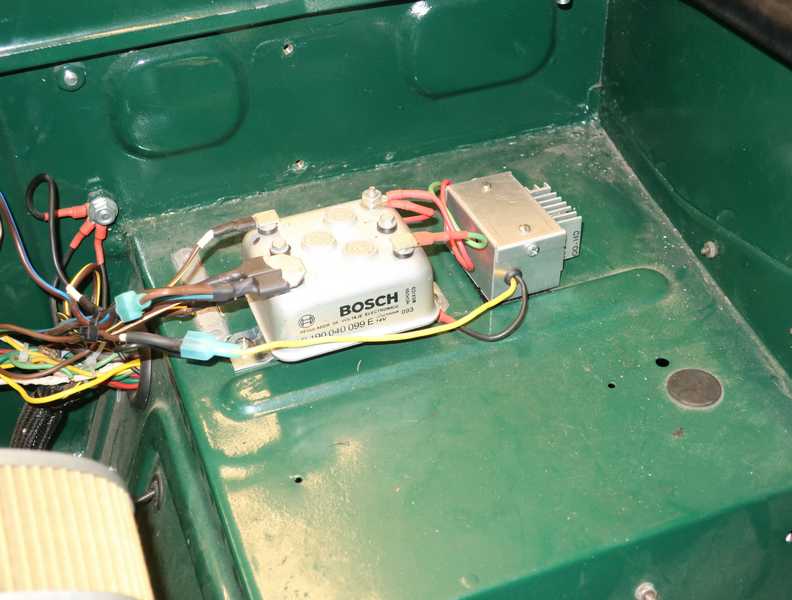
The Bosch 30019 is an electronic regulator intended as an upgrade for older VWs, part no. 9 190 040 099 E. I had one on my Porsche 912 for several years; it was never intended for 912s, but it does work with them, as the VW and Porsche generators are similar. Since the specs of the TR generator are also similar, and I had a Bosch regulator in my box of old Porsche parts, I decided to try one in the TR4A. It's not an expensive unit; I think it's now (mid 2022) $45-$55 most places.
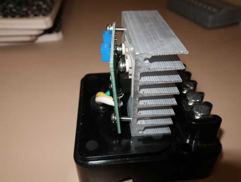
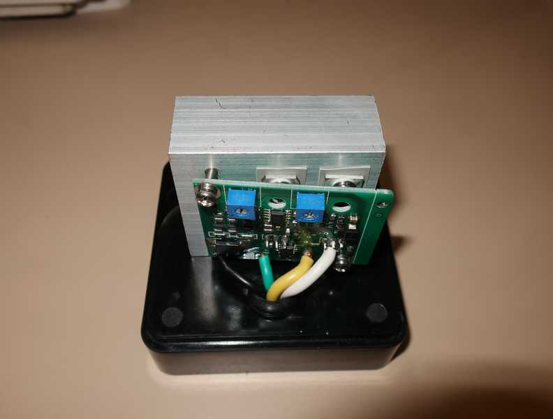
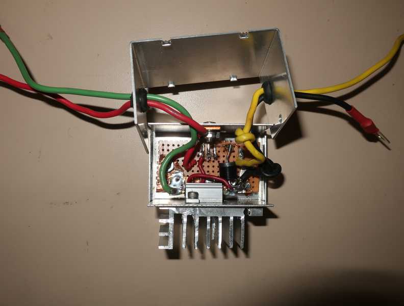
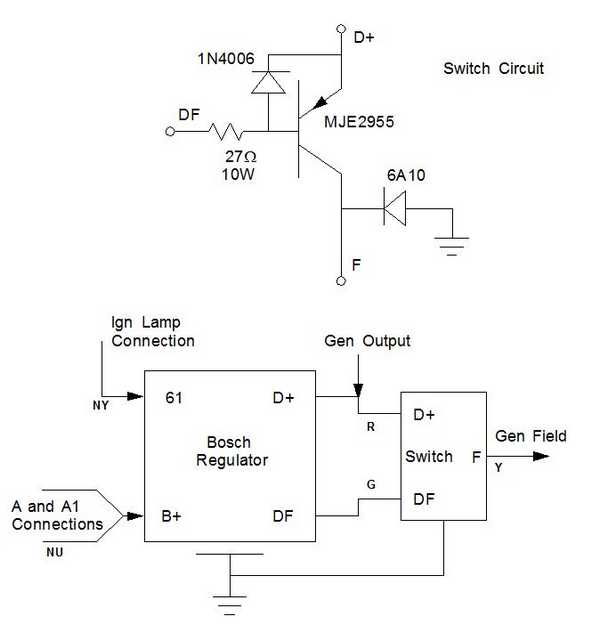
The regulator has one problem for use in TRs: in VWs and Porsches, one terminal of the field coils is powered and they are turned on by grounding the DF (field) terminal; in TRs, and all Lucas generators I have encountered, it is turned on by applying a voltage to the field coil, with the other terminal grounded. Below is the circuit I designed to adapt the Bosch regulator to the TR. The circuit, a simple transistor switch, is in the aluminum box with the heat sink.
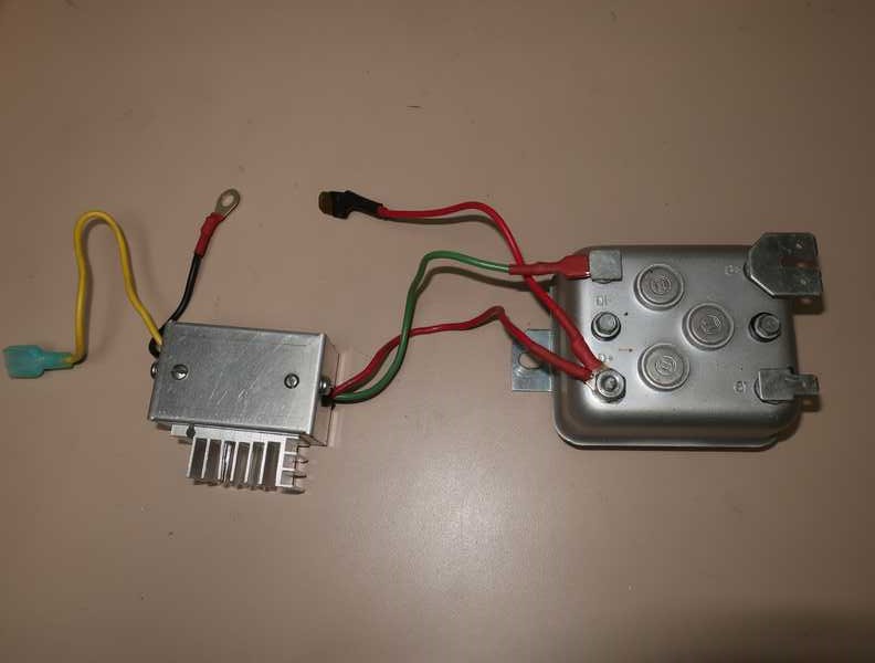
The Bosch regulator's case is "hot" with the generator output voltage, so you have to be careful working around it. (The mounting feet are not connected to the case and are, in fact, the regulator's chassis ground connection.)
The transistor's base resistor dissipates about 5W, so it requires a heat sink. The transistor itself dissipates something well south of a watt, so it doesn't need any additional cooling beyond its mounting on the aluminum box. The 1N4006 diode protects the transistor against possible negative spikes from the generator (unlikely but possible). The transistor's base current is approximately 400 mA; that may seem high, but it is necessary in order to hard-saturate it. It is nowhere near the 2955's base-current maximum, which is 6A. The MJE2955's collector-to-emitter voltage is only 300 mV at 2A collector current.
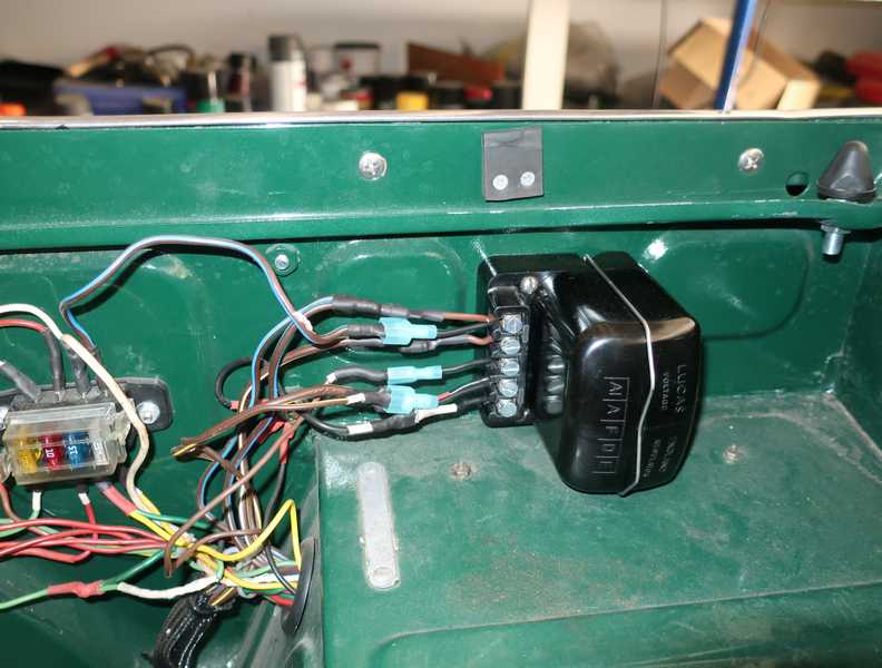
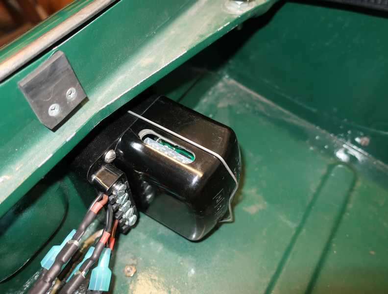
Here it is, installed in the car. Yes, it looks like hell, but I need something that works. The life of my expensive battery depends on it.
From initial tests, the circuit seemed to work well. The system voltage held surprisingly steady at 13.7V to 14.2V, and the charge current was about what I expected, 10A right after starting the car, drifting down to zero over a minute or so. As long as the generator output was great enough, the regulator kept the ammeter right on zero with only a slight (~1A) deviation. On a longer drive, I noticed an occasional jump to the mid-14V range, but I suspect that was just noise upsetting the digital voltmeter. Stopping after a half hour, I checked the temperatures of the switch and regulator. They were warm but not hot; I could still hold a hand on them. I think it's a success.
How to Negotiate This Morass
I'm going to deviate from my rigid policy of not making recommendations and make a recommendation. For those who must have an original appearance, a used, original Lucas RB106 regulator makes sense. It probably will be necessary to repair and readjust it. For a superior, electronic regulator, you could do a lot worse than to reproduce my regulator, described above. These should be fabricated only by people with at least modest experience in building electronic components, as the voltages are not high, but the currents are, and they can cause a lot of trouble if not handled properly. Avoid the modern Lucas stuff; don't reward companies for producing crap.
Outlet Panel
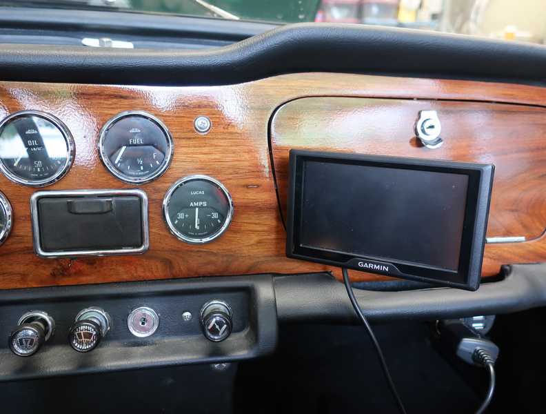
Once I started using the car regularly, I realized that I needed a place to plug in a GPS receiver. I added a panel with a cigarette-lighter socket and received, as a bonus, two USB charge ports. It's mounted with sheet-metal screws and two delrin spacers, which moved the lighter socket low enough to clear the grab handle.
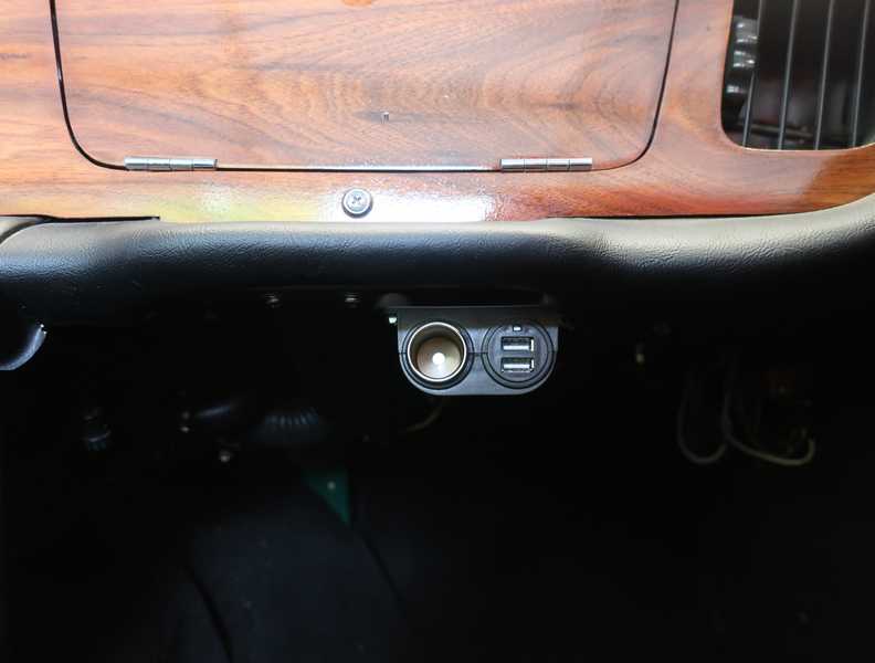
I wired it into an existing circuit, which used one of the fuses in the engine compartment. The GPS needs only about 220 mA, but the charge ports could pull 2A each. Other components in the circuit require something like 5A, so the existing 10A fuse seemed marginal. I increased the fuse rating to 15A.