![]()
External Engine Components
This section describes the restoration of the components external to the engine, including just about anything in the engine compartment.
Click on any picture to see a larger version in a new window.
Contents
- Carburetors
- Fuel Tank Restoration
- Electric Fuel Pump and Pressure Regulator
- Distributor Restoration
- Electronic Ignition
- Radiator and Cooling System
- Exhaust System
- Crankcase Breather
- Starter
- Generator
- Oil Filter
- Miscellaneous External Bits
Carburetors and Fuel System
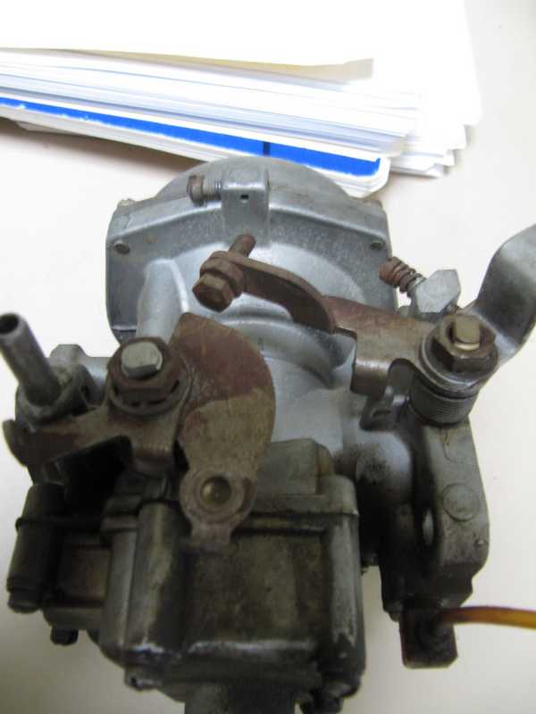
Carburetors
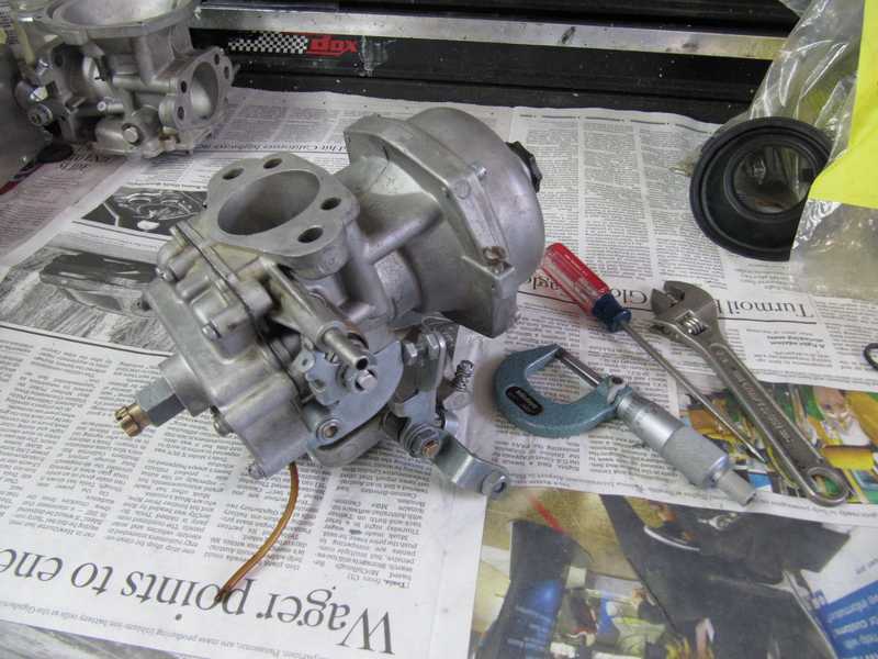
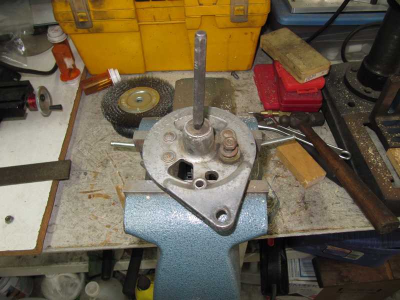
The car had its original Zenith-Stromberg carbs. Although they seemed to be in good condition, they were leaking fuel and were due for a rebuild. On close inspection, both throttle shafts seemed a little loose, so rebushing was in order. I rebushed them in the same manner I used for my MG TD and occasionally for other cars: ream out the carb body, make brass bushings, install them in the body.
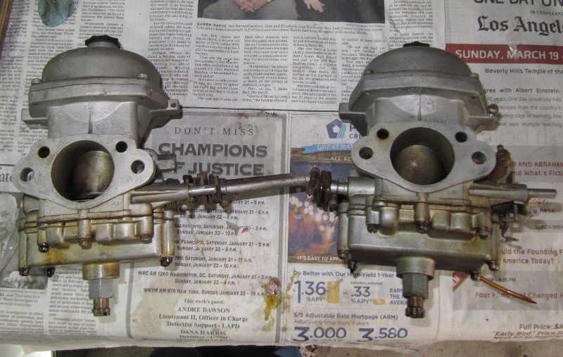
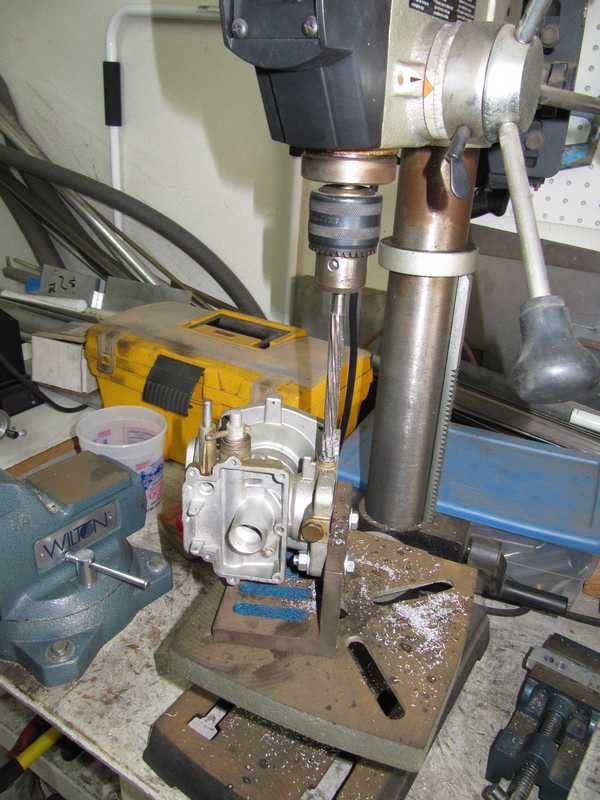
I mounted the body on a right-angle plate for drilling. I reamed the hole to 0.375 inches and made the bushings a little smaller, allowing some looseness for adjusting alignment. To make the bushings, I turned down a piece of 3/8" brass rod to 0.365 diameter, then drilled and reamed the hole. To achieve a good, concentric hole, I first dimpled the end of the bushing with a spotting drill, drilled a 1/8" guide hole and then a ~0.290 inch hole. Finally, I reamed the hole to the desired dimension. I measured the throttle shaft to be 0.311 to 0.312 inches in diameter, so I reamed the bushing holes to 0.3135. Remarkably, the shafts themselves showed no discernible wear.
In the first picture below, the bushings have been installed and cemented into place with JB Weld, a good, fuel-resistant, high-temperature epoxy. The aluminum rod, which I made on my lathe, is a close sliding fit to the insides of the bushings and guarantees that they are in alignment. Since the bushings are only 0.010" smaller in diameter than the holes in the body, there are only about 5 mils of epoxy between the bushings and the carburetor body. The second picture shows the carbs with the assembled throttle plates. I used blue Loctite on the screws, with the appropriate primer, to make sure they won't come loose.
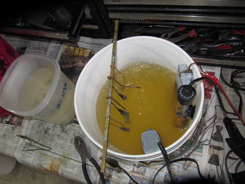
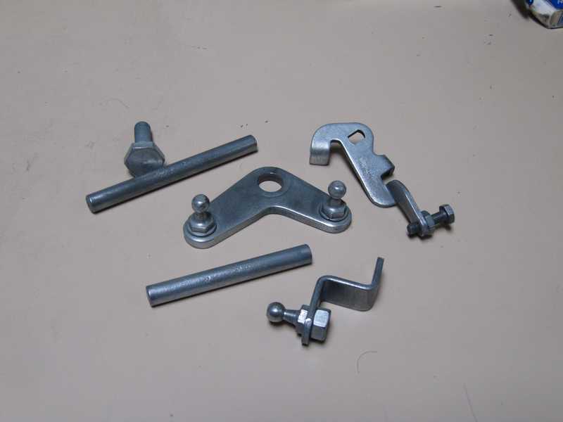
The carb hardware was dull and rusty in places. I replated it using my home-grown zinc plating bath. This is an acid sulfate process, which does not produce a bright finish. The completed part looks more like it has been hot-dip galvanized; it can be brightened well enough for under-hood use by brushing it with a brass wire brush. The last picture shows a few of the replated and brushed parts.
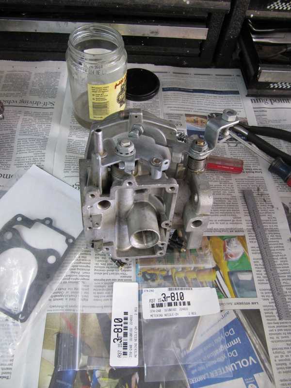
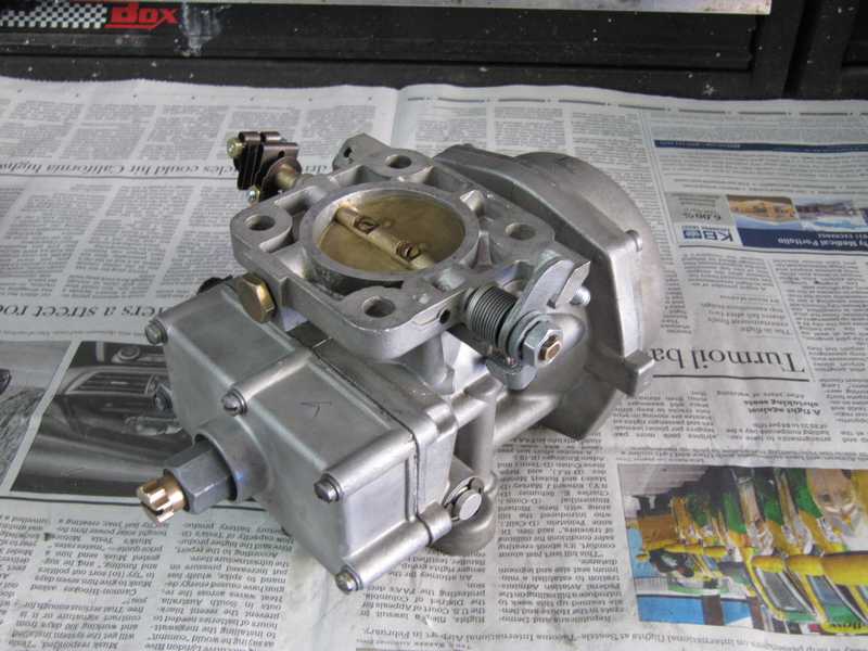
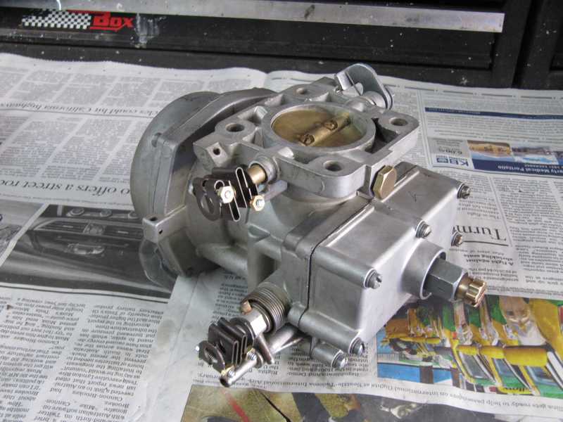
With all the little bits and pieces replated, I continued to rebuild the carbs. With the plating and bushings finished, it was a straightforward job. Below are the right carb being rebuilt and two views of the finished carb.
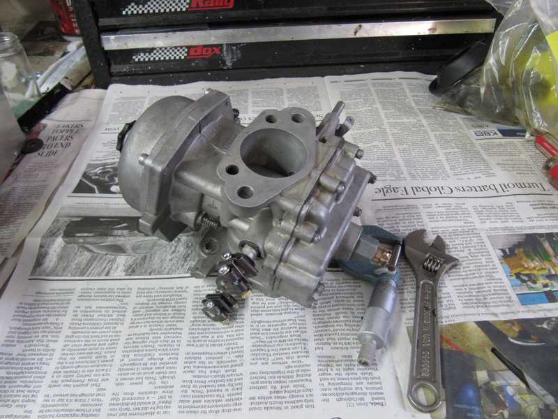
And below is the left carb, ready to go.
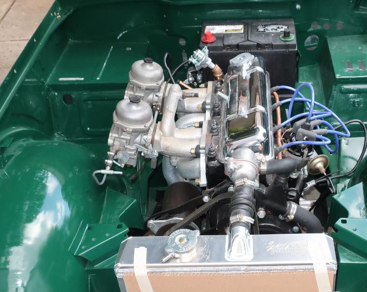
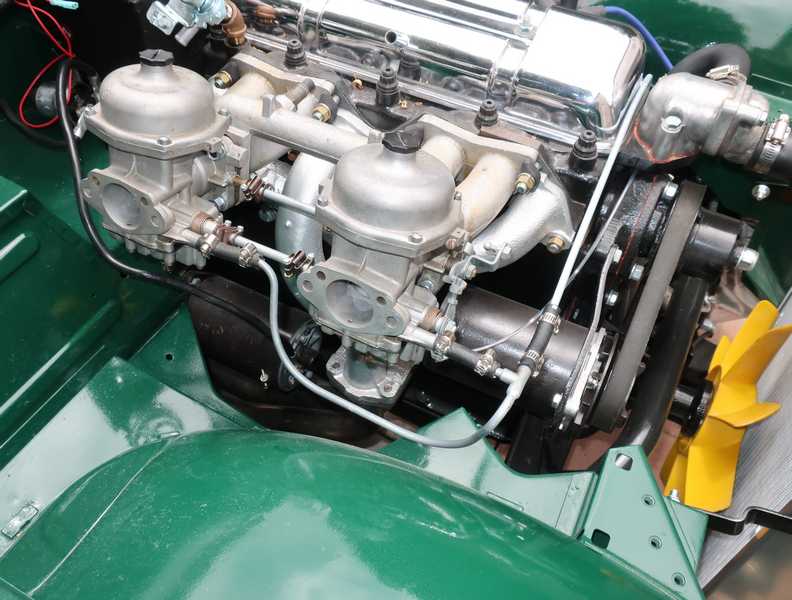
Here they are, much later, mounted on the engine.
A Tale of Two O Rings
When I tried to start the engine, I encountered fuel leaks around the jet assemblies of both carbs, caused by inadequate compression of the O-ring seals. In the pictures below, you can see that the rings barely protrude beyond their grooves, so they are unlikely to seal properly.
The original rings are standard sizes 011 and 114, which are 0.301 x 0.070 and 0.612 x 0.103, ID x thickness, respectively. Even though the groove ID is a few percent larger than the ring ID, it largely compresses just the inside of the ring, so the OD of the mounted ring is only slightly greater than the unmounted OD. Also, the rings have a tolerance of 6 mils on the OD, and my rings seemed to be a few mils undersize. I measured, for example, 0.815 inches for the mounted large ring; its specified OD was 0.818. The bore it sealed against was 0.812; that's not enough compression. The smaller ring's mounted OD was 0.435; the bore was 0.440, so it actually was smaller than the bore!
The next larger English-sized rings were too big, but I found metric O rings that had the right dimensions. I replaced the small ring by a 2 x 7.5 mm metric ring and the large one by a 3 x 15.5. Those provided 10-15% compression.
As you can see in the above picture, the larger O ring probably should have a wider groove, as it will expand laterally as it is compressed. At first, I used the piece as it was, and while it sealed perfectly, it was a little difficult to screw it into the carburetor body, and I was worried that the O ring might get torn after a couple insertions. To solve that problem, I used a lathe to widen the groove by 20 mils, removing material from the side closest to the flats. I also polished the entire groove with fine sandpaper. I did not modify the groove in the brass piece.
The jet assembly now screws smoothly into the carb, without requiring too much force, and the adjuster also moves freely. I'm optimistic that it will work over the long term.
But why was this modification necessary? The carbs originally may have used O ring sizes that are not available today, and the parts floggers just substituted the closest thing they could find. It is also possible that my jet assembly is from a different type of Stromberg carb, but I can't confirm that, as I have no experience with others. I doubt that wear is the reason; if it were, even the new rings probably wouldn't seal well against the worn surface. It's also worth noting that a second set of Strombergs I restored has the same problem.
Later Note
I noticed later that my O rings were made of 70-durometer Buna-N. An O ring with a durometer of 70 is fairly hard; a softer O ring might be preferable, as it would make the jet assembly pieces easier to screw together and the jet easier to adjust. While the 70 durometer is acceptable, adjusting the mixture screw still requires more force than I would like. As I get the opportunity, I will look for something softer.
Accelerator Linkage
The accelerator pedal and its mounts were cleaned and repainted. The linkage pieces were replated.
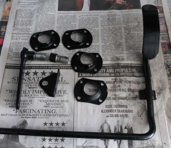
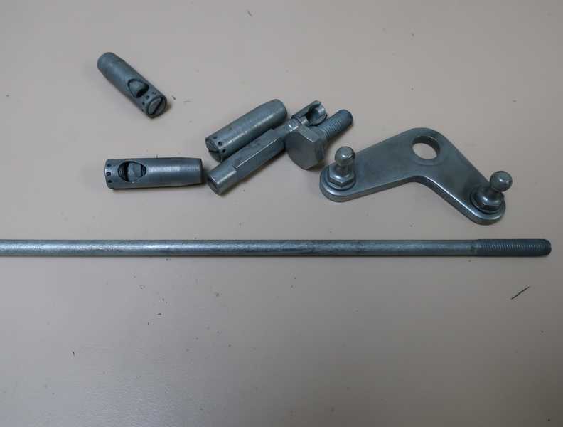
Assembly of the linkage is straightforward, but adjustment is less so. The shop manual has no directions for that, so we're on our own. With some difficulty, I ascertained that the long end of the bell crank goes to the carbs' throttle shaft, and the short end to the long galvanized linkage rod. At first, I started at the (black) accelerator shaft to set up the linkage, but it's probably better to start with the bell crank in the right position (see below), and set up everything else from that.
There was a lot of looseness in the linkage. Some of this is desirable, but too much is not. The bell crank was loose and sloppy, mostly because of wear. I took 10 mils off the mounting screw to remove some of that looseness and adjusted the ball-pivot sockets so they had no looseness but still were light against the ball. The accelerator shaft was a little loose in its nylon bushings; I reused the old ones, but, in retrospect, new ones might have been a good idea. Of course, all the pivot points were oiled.
When I finally got the car on the road, I found that the gas pedal was hard to control. I'd press on it up to a point, with no change in engine speed, and beyond that, it suddenly roared up to a high speed. It was impossible to achieve a smooth throttle response. I fixed the problem by (1) setting up the bell crank properly, and (2) relocating the throttle-return spring, and, most importantly, machining the bell crank to remove the wear that had made it loose.
The bell crank is shaped like an inverted letter "L." The lower arm of the "L" must point straight down; if it is a little forward of the correct position, difficult throttle control results; if it is rearward, there isn't enough linkage motion to open the throttle completely (and we do want to open it completely, don't we?) Finally, the crank simply had too much wear at the pivot. I machined it smooth, removing maybe a total of 20 mils from both sides, and modified the pivot so the crank moved smoothly but without looseness. Getting this right made a huge improvement in the throttle response.
The throttle-return spring normally attaches to a tab below the lever; that's not really optimum. I moved the attachment point to the exhaust manifold, as shown below, and that helped to improve the response.
Fuel Tank Restoration
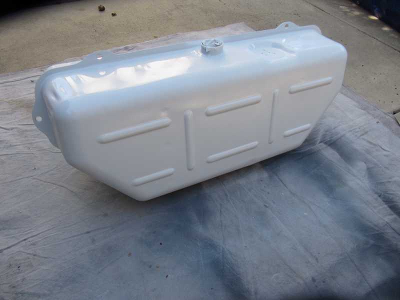
The fuel tank looked good inside: little rust, and the galvanized coating was largely intact. It had some resin on the lower outside, left over from the fiberglass repair of the spare-tire well. That had to come off, along with some crud on the underside.
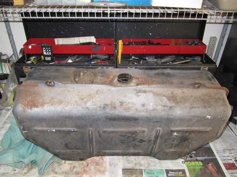
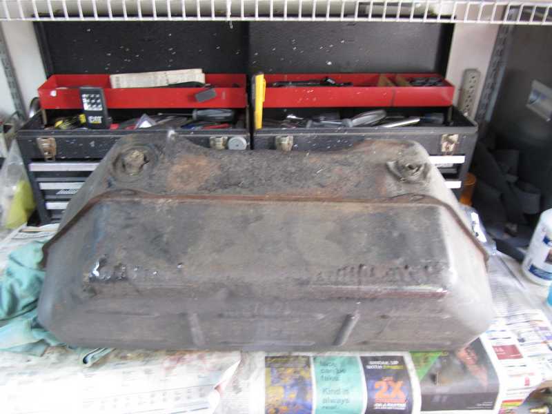
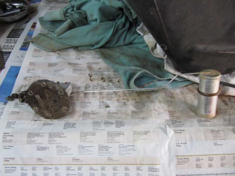
I took out the sending unit, which seemed OK visually. The flange needed some serious cleaning.
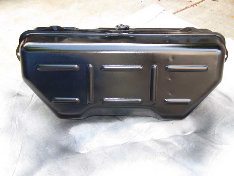
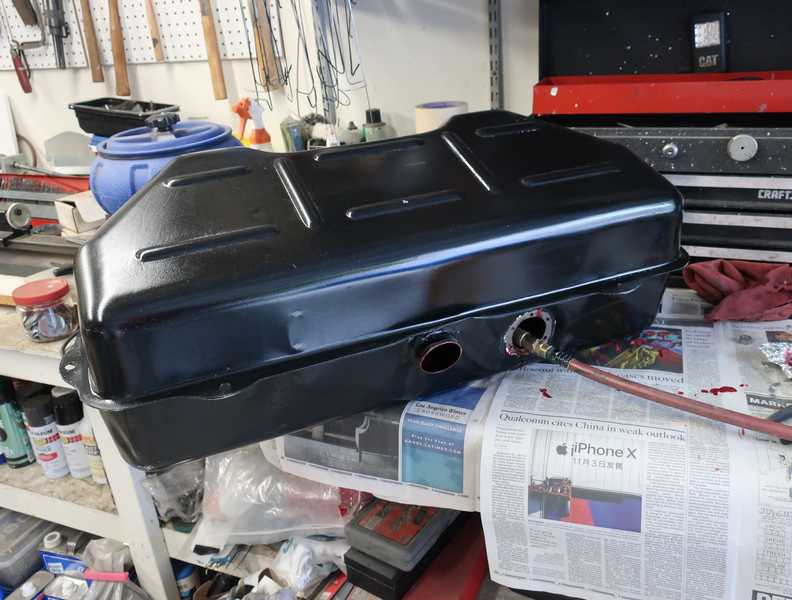
I took off the resin, crud, and paint with a wire wheel on my angle grinder. Under the crud layer, on the bottom, I found significant rust pitting and a few pinholes. From what I've seen, this is a common condition of old TR fuel tanks. The stuck-on crud was the only thing preventing the tank from leaking!
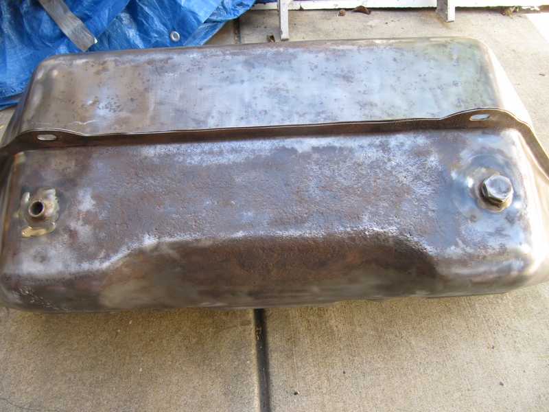
To fix the leaks, I sandblasted the corroded area, then tinned it and coated it with body solder. Because of the shape of the repaired area, I couldn't smooth out the body solder in the usual manner, with a special file. Instead, I gave it a coat of body filler and sanded it smooth.
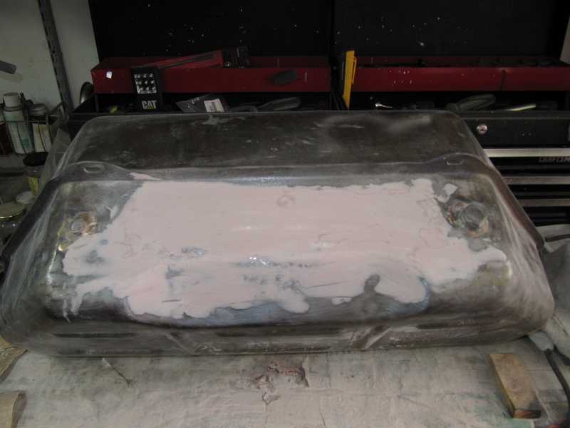
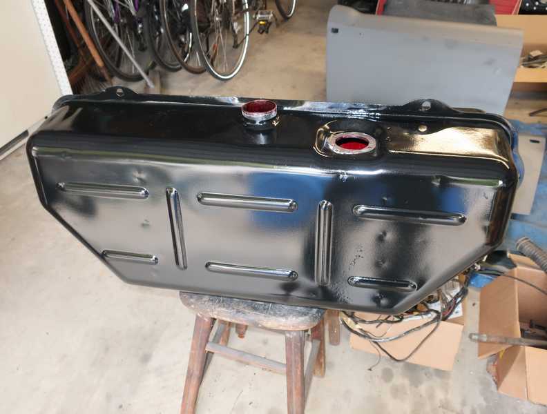
I gave the tank a couple coats of Rustoleum primer, then a finish coat of semigloss black Rustoleum, the same paint I used on the frame. I thinned it about 10% for spraying.
Coating and Sealing the Tank's Interior
During the year or so between restoring the fuel tank and installing it, I became progressively more concerned about the rust and pitting on the bottom of the tank. Although I felt confident that I had soldered all the pinholes, it was still possible that an undiscovered pinhole might yet be lurking among the rust pits. With that in mind, I decided to coat the inside of the tank. Ideally, this should be done before the tank is painted, as some of the substances used in the coating process can damage paint. Doing it at this stage just requires more care, or possibly another coat of paint. There are a number of tank-lining materials available; I chose Red Kote Fuel Tank Liner, as it was recommended by a person I trust.
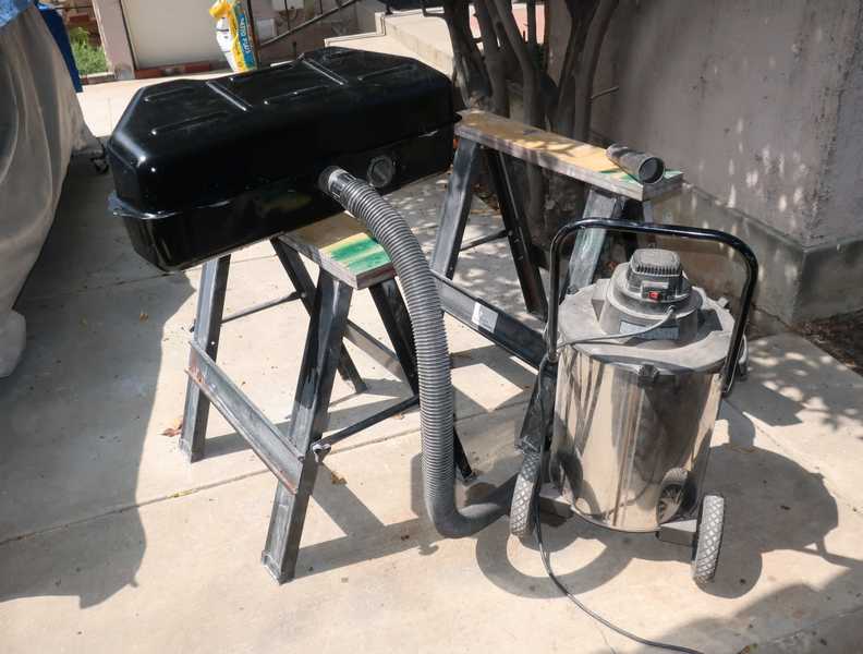
I started by washing the inside of the tank with acetone to remove residual gasoline "varnish," the hard, yellow layer that always seems to develop wherever gasoline is used. Per the instructions, I then filled the tank with detergent solution, letting it sit for an hour with occasional agitation. After that, I drained it perhaps 80%, turned it over so the upper surface also would be cleaned, and repeated the process. After emptying the tank, rinsing it thoroughly, and draining it as well as I could, I connected my shop vacuum so it would suck a hurricane of air through the tank. That dried it completely in less than a half hour.
I didn't use any rust remover on the inside of the tank, as it had minimal rust and the product's instructions claim that it will encapsulate light rust.
My one-quart can of the sealer was completely adequate for the TR's 12-gallon tank. The stuff is pretty thick but flowed well, so it was not difficult to coat the entire inside, including the baffles, by tilting the tank back and forth. Getting it all out was more difficult, as the filler tube extends into the tank about a quarter inch, so it is impossible to empty the tank via the filler. I had more success using the hole for the fuel-level sender; the drain hole and fuel outlet were too small for draining the thick stuff out of the tank. Emptying the tank completely is important, as the instructions warn us sternly not to allow puddles to form. I reclaimed about half of the sealer, which can be reused.
Once I was happy that the tank was well drained, I stuck an air hose from my compressor into it to help dry the sealer. I arranged the tank to allow any excess sealer to flow toward the top and spread out, so no puddle would form.
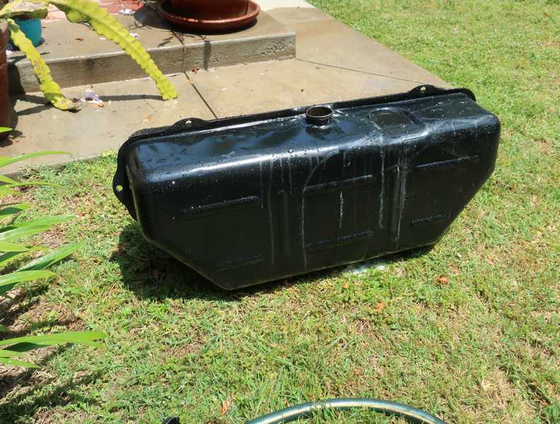
The front of the tank was a little beat up from all the handling, so I sprayed another coat of paint on it.
I was happy with the coating. It seemed to be thick and hard, and it should give me what I wanted from it.
Below, the tank mounted in the body. Since it's chrome and could have been marred easily, the fuel filler cap wasn't installed until later. (I made sure that the filler was covered, though, to prevent debris from falling into the tank.)
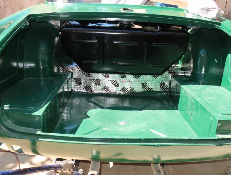
The new fuel filler hose was thicker and less flexible than the original, making it a bitch to install. I found it easier to insert the hose from the passenger-compartment side of the tank. If the old one had been in adequate condition, I would have used it instead.
By the way, the tank's outlet connection is a BSPP thread, 1/4-inch nominal size (per my memory, which is not all that reliable) and takes a standard 5/16 OD tube and ferrule.
Electric Fuel Pump and Pressure Regulator
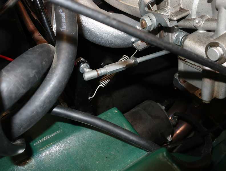
I don't like mechanical fuel pumps, as their outlet pressure is not adjustable and often too high; then they can force fuel past the carbs' float valves and cause flooding. Instead, I like to use an electric fuel pump with 6-7 PSI outlet pressure and a pressure regulator, which I set to about 2 PSI, ahead of the carbs. The higher pump pressure provides a good pressure drop across the regulator, resulting in a constant fuel pressure at the carbs. It also raises the fuel's boiling point a bit and may help prevent the formation of vapor bubbles in the fuel.
In the past, I've used a Facet "cube" electric reciprocating pump. It's a good pump, but it's noisy. This time I tried a Carter P4070 rotary-vane pump, a bit more expensive and a lot larger, but also a good unit. Its outlet pressure is rated at 4-8 PSI and flow at 72 gallons per hour (GPH). I mounted it under the car, on the rear wall of the passenger compartment. The pump is designed to be mounted in an exposed location, but I imagined that mounting it on a rearward-facing wall of the body might protect it a little.
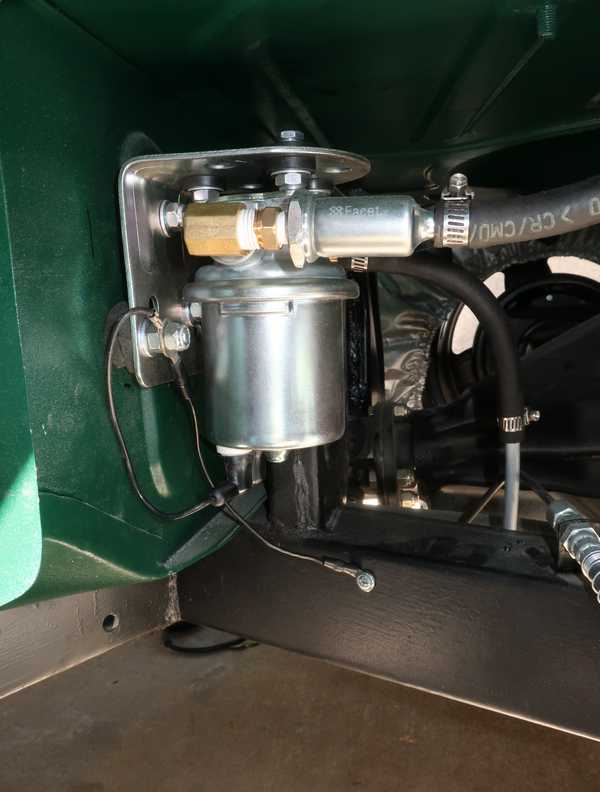
The pump is mounted on its bracket with rubber isolation disks. To provide a little more isolation, I also cut rubber disks to fit between the bracket and car body. The cylindrical item at the pump's inlet is a wire-mesh filter; it is necessary here, as there is no mesh filter in the fuel tank. Even if there was one in the tank, it wouldn't be a bad idea to install one of these anyway, as there is no way to check the tank's filter for damage. The electrical power line comes through a small, grommeted body hole on the far side of the pump. The pump's negative terminal is grounded to the frame through a self-tapping screw. Connecting the ground line to the bracket, as well, makes all the mounting bolts acceptable ground points, which may be useful.
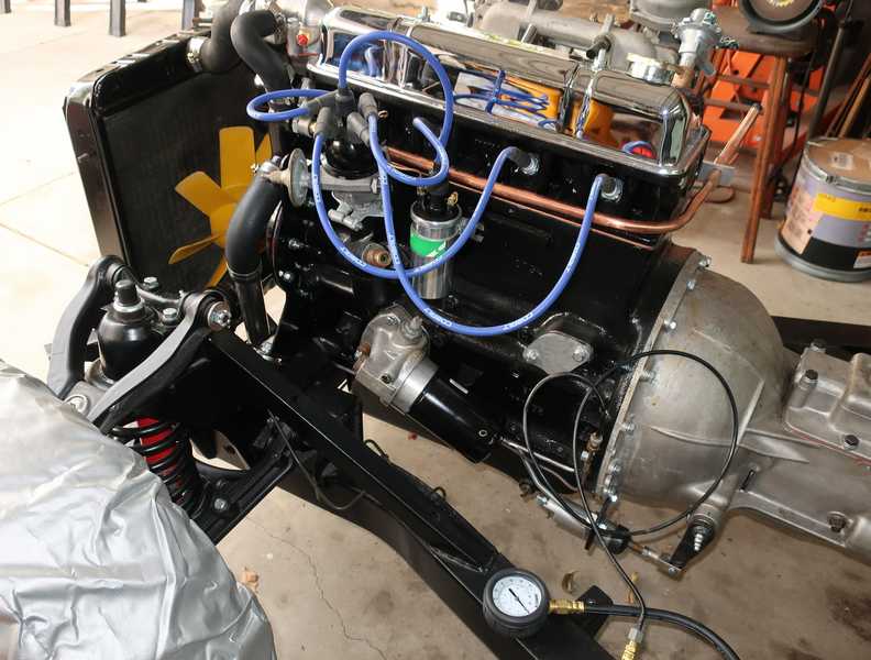
Below left, the pressure regulator. It's a Holley 12-804, which has an adjustable outlet pressure of 1 to 4 PSI. I installed a pressure gauge permanently, so I can check the fuel pressure without the hassle of hooking up an external gauge, and, of course, a fuel filter, located on the cooler side of the engine compartment. The second picture shows the rest of the fuel-line installation.
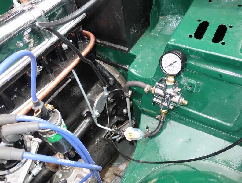
While everything was still accessible, I put a couple gallons of fuel into the tank, ran the fuel pump, checked throughout for leaks, and adjusted the pressure regulator for an output pressure of 2 PSI. All was good.
A Note on Fuel-Pump Pressure and Flow
People regularly confuse fuel-pump pressure and flow. When I tell them that I operate with ~2 PSI at the carbs, they ask how I can be sure that there is enough flow at that low pressure. That's nonsense, as low pressure does not imply low flow; in fact, the opposite is true.
Below is a plot of pressure (X axis) vs. flow (Y axis) for a number of the Facet cube pumps. (Unfortunately, I could not find a similar curve for the Carter pump.) Note that the outlet pressure is highest at low flow, and lowest at high flow. That's to be expected: any pump is limited in power, and power is flow times pressure, so high flow must result in lower pressure, and vice-versa. Reducing the pressure with a regulator affects the flow only minimally.
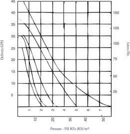
The rated pressure is the outlet pressure at zero flow. The rated flow is at zero pressure. The effect of the regulator is to "clip" the curve at the outlet pressure; i.e., instead of decreasing gradually as you move to the right on any of the above curves, they drop precipitously at the outlet-pressure value set by the regulator. In essence, the effect of the regulator is simply to limit the pressure at the lower rates of flow.
The outlet pressure of the regulator needs only to be high enough to raise the fuel from the regulator to the carbs (here, just a few inches) and to overcome the minor pressure drop in the lines, the filter, and the carburetor's float valve. A couple PSI is plenty for that; more just causes problems.
Why on earth would anyone need 72 GPH flow? After all, if the car gets 20 MPG, it would use 72 GPH only at 1440 MPH! I don't think I'll drive the TR4A quite that fast. Still, it makes sense, for a couple reasons: first, 72 GPH is something of a fictitious number, since it applies only to zero pressure, and you need pressure to move the fuel. More to the point, though, it keeps the float bowl full when there is a large surge of fuel use. Think of 72 GPH as 2.56 fluid ounces per second. It's easy to imagine the engine using fuel at a rate of an ounce or two per second at maximum rotational speed and full throttle. Without an adequate flow rate, the fuel level in the float bowl would drop and the engine might stumble.
Distributor Restoration
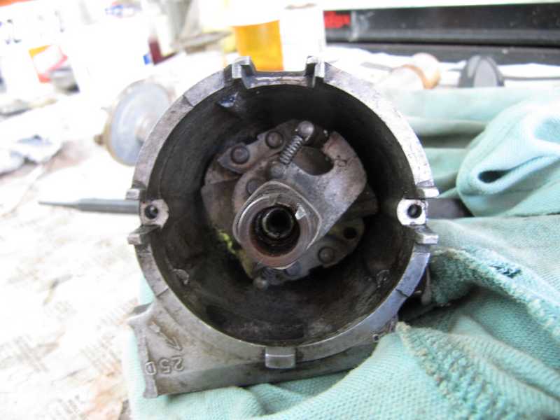
The TR4A uses a Lucas 25D distributor, model 40795A. This distributor was the correct model, probably an early replacement, as it had a 1966 date code. It seemed OK, just very dirty, so I took it apart to clean it. The two screws holding the breaker plate to the body (i.e., the screw holes visible in the second picture below) are size 4BA; it's important not to lose or damage them, as they're not easy to replace.
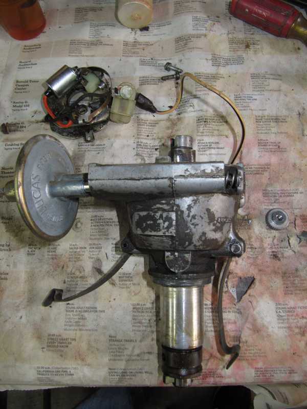
Disassembling, cleaning, and reassembling the distributor is straightforward and well described in the shop manual, so there isn't much point in showing the details of its restoration. The disassembled distributor is shown below. Because the pin holding the drive dog to the main shaft was quite tight, I didn't attempt to remove it. It isn't necessary, anyway, as long as the shaft bearing is smooth and not loose, and the end float is not excessive. Lucas specifies the end float as 31 mils, maximum; I measured 21. I could not feel any looseness at all in the bearing. I lubricated the parts appropriately as I put the distributor back together.
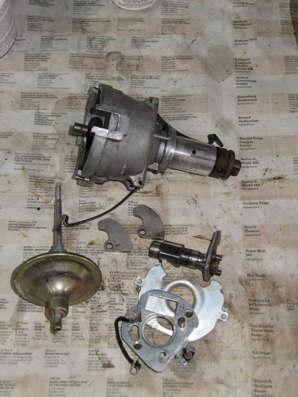
I have since read that the drive dog's pin is tapered. I hadn't noticed that, but if that is correct, the pin can be removed in only one direction. If I ever work on another one of these, I'll keep that in mind.
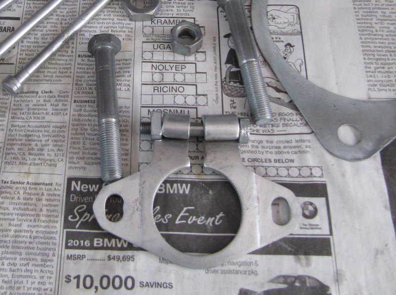
I replated the distributor clamp and its special bolt. The other parts in the picture, which I replated at the same time, are from the starter and the generator.
Completed, the distributor looked much nicer, and the mechanical and vacuum advance both worked smoothly. I didn't have access to a distributor machine, so I couldn't check the advance curves, but later, when timing the car, I could see that the centrifugal advance was working and the total advance was correct.
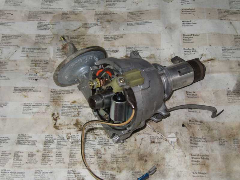
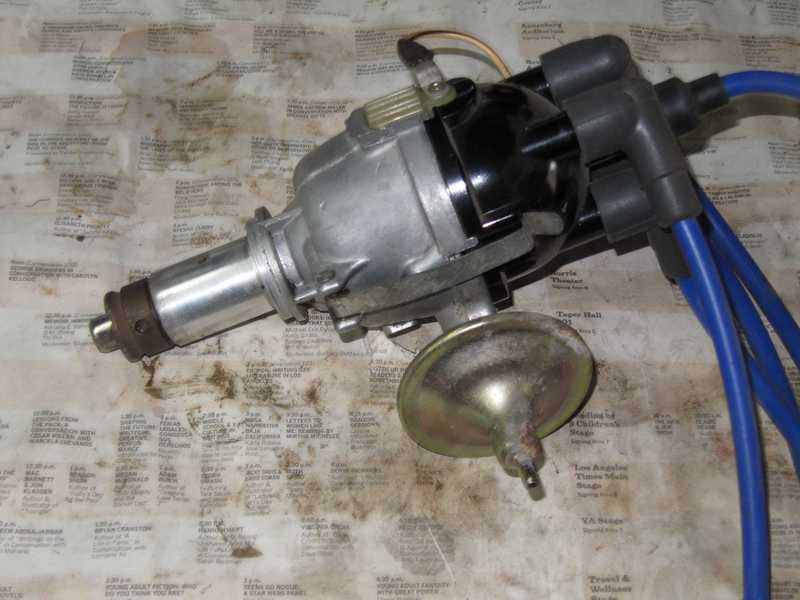
That's not the usual type of distributor cap, and the blue wiring looks a little odd. But it's a high-quality ignition-wire set, so I may just keep it.
A Note on TR Distributors
According to my best information, the TR4A had only this one model of distributor for all cars having normal compression. (The TR4A was available with a low-compression engine option for parts of the world with low-quality fuel. Those, now very rare, had a different model.) TR4s had a couple, all of which were type DM2P4 in various models; most TR4s, 1961-65, used the 40734A. Even though the TR4 and 4A engines were virtually identical, there was a significant difference in their distributors' advance curves. Those changes may have resulted from further engine development work or gradual improvements in gasoline in the postwar UK. As such, it probably makes more sense to use a later distributor in an early car, rather than vice-versa.
A Second Note: Vacuum Advance
The vacuum-advance unit on the distributor is an important item, yet many people assume that it's not particularly critical. Parts suppliers often offer a single replacement unit for all 25D4 distributors, even though the advance specifications differ significantly among the various models. I have to confess a similar carelessness, as I never checked the vacuum advance when I rebuilt the distributor. I just reused the existing one, checking only that it was not leaking or stuck.
The advance unit on my distributor was type 54411968, which has a "5-12-8" specification. That means the advance starts at 5" vacuum, reaches its maximum at 12", and the maximum advance is 8 degrees at the distributor. This is typical of replacement units; only a few suppliers offer replacement units that are correct for individual distributors. The correct advance unit for the 40795A is Lucas type 54413565, specified as 2-6-3. The shop manual confirms this spec. That's a big difference.
It is possible to find new-production, replacement distributors, but I have never seen vacuum or mechanical advance data listed in a listing for one. I would not buy one unless the seller could clearly state all advance specs.
I discovered this on my first highway trip when I noticed pinging at cruising speeds with a light throttle. I had to keep the speed down to about 50 MPH in overdrive to prevent it. It was clear, once I got home and looked into the situation, that the vacuum advance was far too great, causing the pinging.
A couple suppliers offer units specific to the distributor: Rimmer Bros. is one, Moss is another. Rimmer's price is good, but it entails high shipping costs from the UK, and, possibly, tariffs. Typically, Moss offers a moderately overpriced "standard" unit and wildly overpriced special units, hand-built by Black Forest elves or some such thing. BP Northwest offers only a single unit for all distributors. I ordered a new, correct vacuum unit from British Vacuum Unit.
Electronic Ignition
To keep things simple at the outset, I used the conventional points and capacitor ("Kettering") ignition for the car's first few hundred miles. I always intended to use some kind of electronic ignition, so, to begin, I built a simple electronic unit. I quickly got interested in the problem of creating electronic ignitions for older cars, so I tried several approaches.
First Circuit
The circuit I used is that of W. Kahan, reproduced below. Many of the recommended parts are no longer available (the circuit, after all, dates from the late 1960s), so I found acceptable substitutes. The original article specifies a germanium PNP transistor. Germanium power transistors have a low collector-to-emitter voltage when saturated, an advantage in this circuit. They were common in the late 1960s, but not so much today; my substitute is a PNP silicon device, the MJE15033. The zener diodes are 1N5378B (100V, 5W), and the BE protection diodes are 1N4006. I used a 2.2 mH inductor rated at 400 mA (100 mA would have been plenty), with 4 ohms series resistance. The circuit description specifies 10-15 ohms series resistance, so I added a 10-ohm resistor in series with it. Somehow I got it into my head that this resistor would carry more current than it actually does, so I installed a power resistor. That's not necessary; even a quarter-watt resistor would have been fine. There is nothing magical about this resistance; its purpose is simply to limit the current in the inductor. The capacitor C is a 0.22 uF, 1000V polypropylene unit. 1000V is greater than necessary, but it's what I had available. A breakdown voltage of 250V would have been plenty. It is important to use some kind of high-current film capacitor here, as a dinky little radio cap won't work. This capacitor's dV/dt rating must be at least 25V/uSec. Any acceptable capacitor will cost a few dollars.
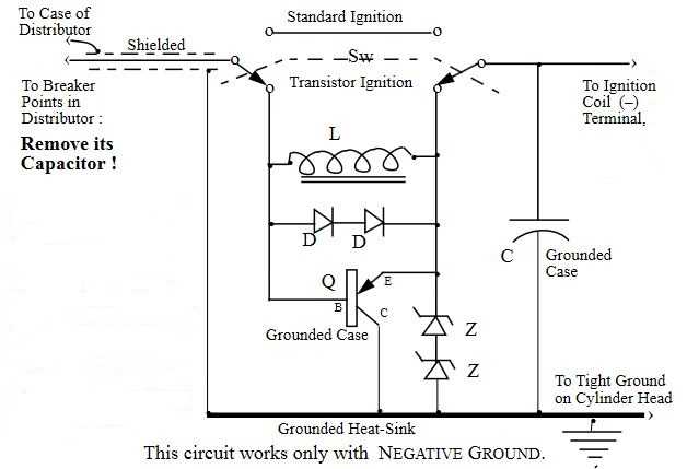
The purpose of the inductor L is to speed the transistor's turn-off by establishing a current that discharges the transistor's stored diffusion charge. The diodes D protect the base-to-emitter junction.
As noted, the circuit works only with negative ground. It could be converted for positive ground by reversing all the diodes, replacing the PNP transistor with an NPN one, and reversing the coil connections. The MJE15032, the NPN complement of the MJE15033, should work in a positive-ground version of this circuit.
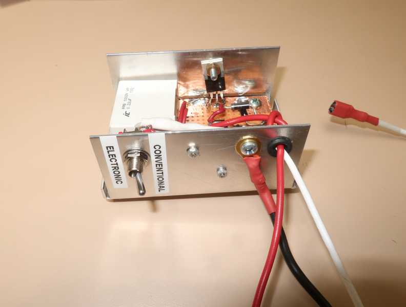
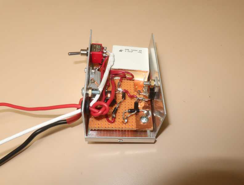
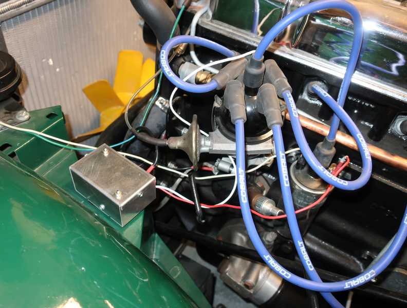
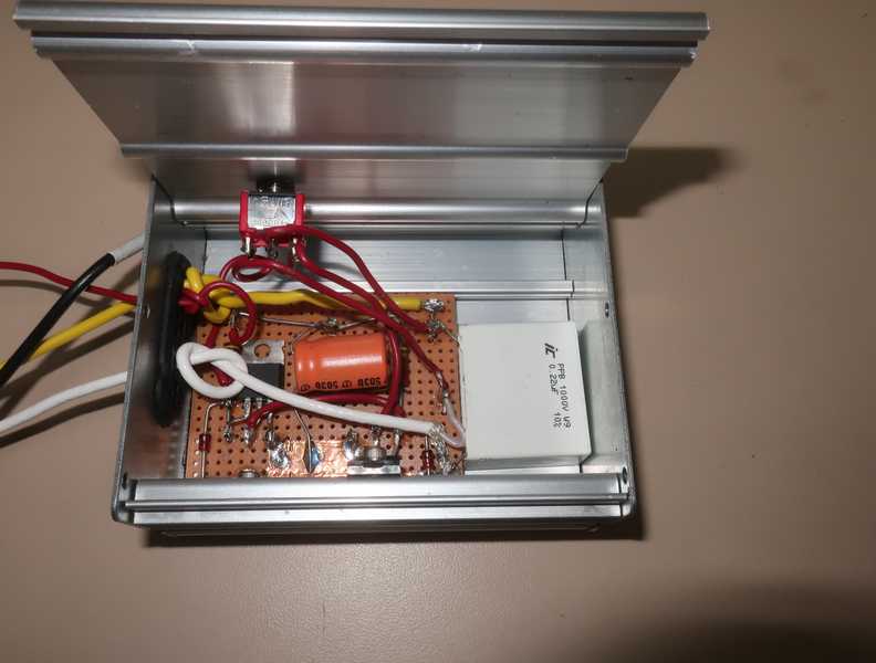
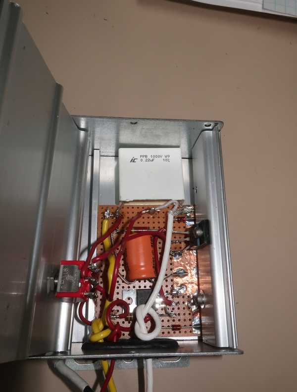
Below, the finished ignition module. The circuit is built on perforated board with "flea" clips for connections. A printed-circuit board would be preferable for the final circuit, but fabricating one is too much trouble for this experimental version. The transistor is mounted on the aluminum box; I don't think it needs more heat sinking than that, as it should dissipate only about two watts. The red and white wires connect to the coil and points, respectively, and the black is an engine-block ground connection.
For testing, I mounted the module in the engine compartment with velcro as shown.
The switch on the side of the box allows the ignition to be returned to conventional points-capacitor system if something in the electronics fails. One should not switch between modes when the engine is running, as this will shut down the ignition for a few engine revolutions, likely resulting in an impressive backfire. It might also create a transient that could damage the ignition module.
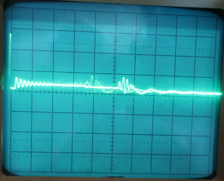
The waveforms obtained with this circuit are interesting. The two photos below show the voltage across the capacitor, C. With conventional ignition, the waveform is what we usually expect: an exponentially decreasing sinusoid at first, suddenly changing to a lower-frequency sinusoid when the spark is extinguished. The peak voltage is a bit over 200V. The oscilloscope is set at 100V/cm and 0.5 mSec/cm, and the trace, unfortunately, is not zeroed perfectly.
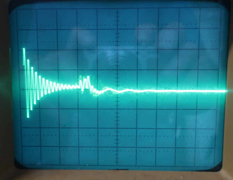
I'm not sure what causes the oscillation at ~1.5 mSec, just as the spark is extinguished. I haven't noticed this on other cars.
With electronic ignition, the waveform is a rectified sinusoid. The clipping of the negative peaks is probably caused by the zener diodes in forward conduction. The peak voltage is just under 200V, but the voltage stays high longer than in conventional mode.
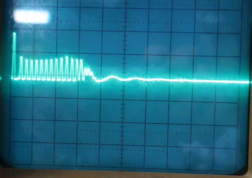
I never entirely understood the reason for the difference in the waveforms. The zener diodes obviously clip the waveform, but the striking difference between the two waveforms is hard to explain. It may be caused by the inductor (L) and the two diodes (D); in simulation, obtaining a similar waveform was possible, but it required much larger values of L than I actually used.
It's not unusual for electronic ignitions to have different waveforms from conventional ones. The important thing is the spark energy, which can't be higher with this type of electronic ignition (both types are limited by the same thing: the ignition-coil primary current), but must not be lower. It's hard to say, from anything you can measure with an oscilloscope, what the relative spark energies are. Since I couldn't measure the spark energy directly, I simulated it on SPICE. Although there was some discrepancy between the measured and simulated waveforms, I found that the spark energies resulting from the conventional and electronic circuits were almost identical.
Two things about this circuit I don't like: (1) the current in the points is 480 mA, which is much better than the ~4 amps in a conventional ignition system, but still more than I want; and (2) the collector-to-emitter voltage is fairly high, 1.1V. (The voltage across the coil is reduced by this amount, slowing the rate of its current build-up and limiting its maximum current, so it should be kept as low as possible.) These are largely consequences of using a silicon transistor instead of the originally-specified germanium one, but we can use only what's available today. Today's high-voltage power MOSFETs, however, can ameliorate the situation considerably.
Second Circuit
Next, I tried a circuit that uses high-power switching MOSFETs. These devices have the advantages of faster switching, without requiring the inductor of the BJT circuit; much lower current in the points; and lower voltage drop in the switching device. The circuit is shown below.
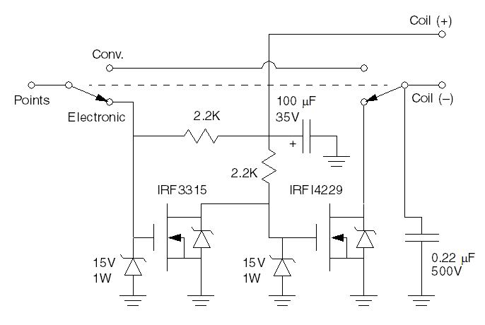
The circuit is straightforward, an inverter followed by a device that switches the coil current. I used a power device for the inverter, as its high current and low ON resistance ensure that the following device, which has a fairly high gate-to-source capacitance, switches rapidly. Switching time should be only a few microseconds. Since one degree of crankshaft revolution is 28 uS at 6000 RPM, the switching delay should not measurably retard the ignition timing, even at high speed. The points interrupt only the 12V system voltage and never carry more than 7 mA; in contrast, the points' current in the first circuit is almost half an amp. The measured drain-to-source voltage of the big MOSFET is only 0.25V, compared to 1.1V for the first circuit's collector-to-emitter voltage.
The IRF3315 and IRFI4229 are low-cost Infineon power MOSFETs. It might be possible to use a smaller device in place of the IRF3315, but there is little to gain (maybe $1-2 in cost savings) in doing so, and it could increase the switching time. The FETs have internal zener diodes to protect their channels; I added 15V zeners (1N4744s) to protect their gates, as well. The IRF3315 dissipates little power, only milliwatts, so it is not mounted on a heat sink. The IRFI4229 is mounted on the wall of the housing, which affords good heat sinking. As with the previous circuit, an engine-block ground is essential, the distributor's ignition capacitor must be removed, and the 0.22 uF capacitor must be a high-current metal-film device. This circuit is negative-ground only; a positive-ground version would require acceptable P-channel FETs (I have no suggestions), reversing the diodes, and reversing the polarized capacitor. A switch allows operation to be returned to conventional ignition.
The input impedance of the inverter stage is relatively high, so I decided that it was prudent to use shielded line for the connection to the points. That should help to prevent the device from being triggered by noise.
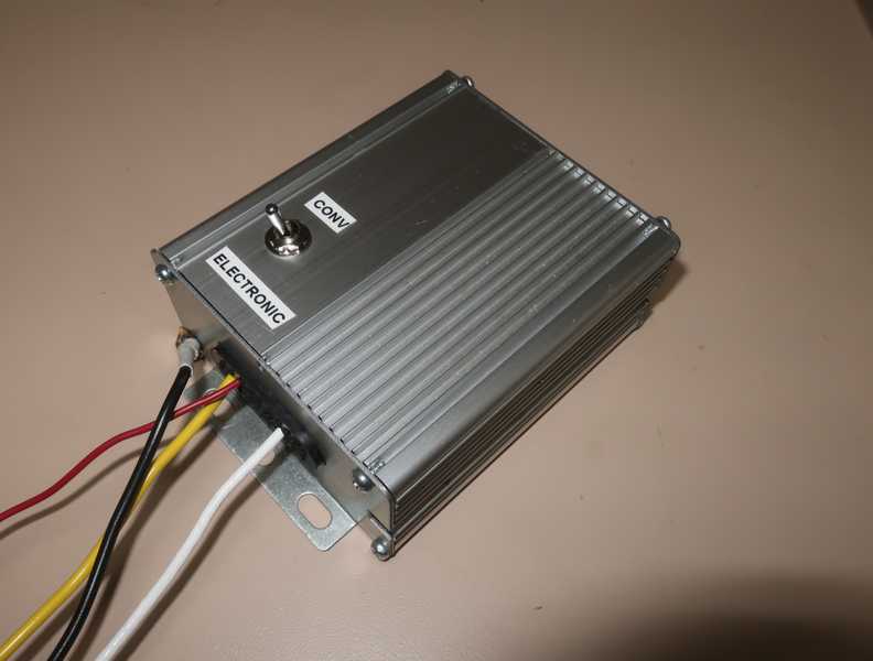
The housing is one that I had salvaged from some other equipment. It makes a nice package, I think.
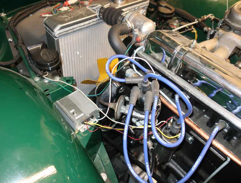
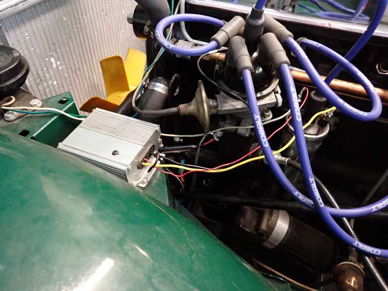
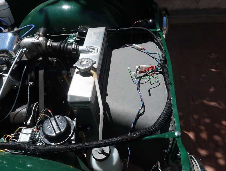
I decided to use this module in the TR4A, so I mounted it permanently. I would have preferred a less visible location, but this was the only mounting that made sense.
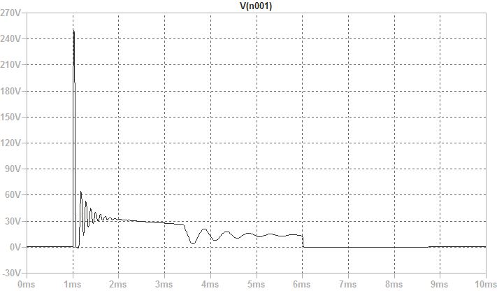
Finally, here is the waveform for the voltage across the capacitor. It is a little surprising: one pulse of 250V, followed by a much smaller oscillation. Again, this is 100V and 0.5 mSec per division.
One open question is how the spark energy obtained with the electronic module compares to that of the conventional system. It seemed unlikely to be greater, as both were limited by the same thing (coil current), but it could be lower. It was difficult to determine this from anything that could have been measured with an oscilloscope; trying to make direct measurements at the plug was unlikely to be successful. Instead, I simulated the circuits on a widely used circuit simulator, LTSPICE. Following Holden, I modeled the coil from measurements and treated the spark gap as a pair of zener diodes. Below, the calculated capacitor voltage, which agrees well with the plot shown above. (Note that the plot scale is 1 mSec per division.)
I found that the calculated spark energies of the two circuits were the same, within the validity of the calculations, although probably higher than reality. I suspect that the coil's core losses make up some of the difference and, in the conventional circuit, arcing at the points probably eats some energy, too.
With either of these units, it is possible to have full current in the coil when the ignition is turned on but the car is not running. To prevent coil heating, it is best not to leave the ignition on, without the engine running, for more than a few minutes. When this happens, the BJT or high-current FET will also be turned on; the heating in those devices will be about 4W for the BJT or 1W for the FET. This situation is no different from conventional ignition, of course, where leaving the ignition powered can overheat the coil, but it is still worth noting.
A Later Note
This ignition circuit has been reliable. I can't say as much for the switch, which failed once. I believe that it could not take the vibration and temperature variations of the engine compartment, and its current rating was marginal. Ironic, isn't it: the system's one electromechanical component, included to improve reliability, was the cause of its only failure.
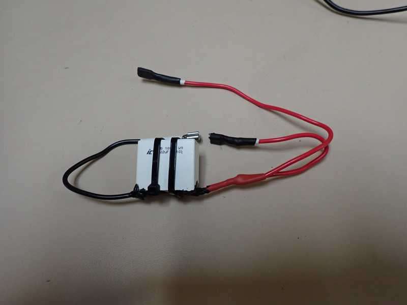
I removed the switch completely. I made up a 0.22 uF capacitor, like the one in the electronic ignition circuit, with wires and 1/4-inch spade connectors. I have it in my toolbox, and if the ignition fails, I simply disconnect the ignition module and connect the capacitor. That gives me a standard Kettering ignition. However, I doubt that I'll ever need it.
Radiator and Cooling System
Radiator
This turned out to be a fiasco. I went to quite a bit of trouble to restore the radiator, but it wasn't until I installed it on the engine that I learned it was unusable. Anyway, here's the story.
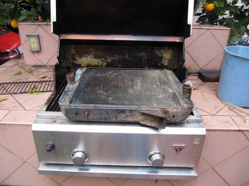
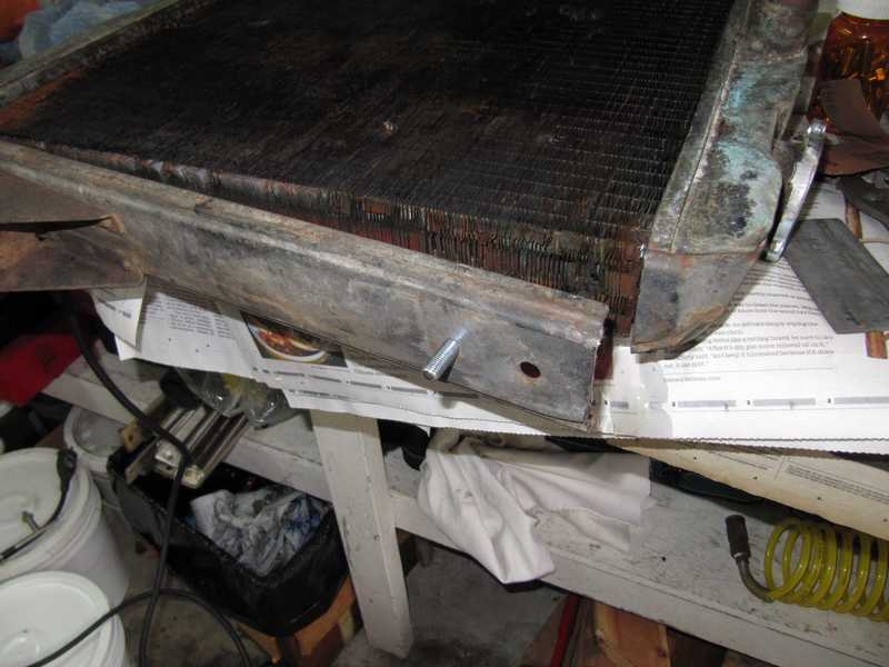
The radiator seemed usable, with no sign of leakage, but it still needed some help. Like many 60-year-old radiators, it was gunky inside and had some cooling-fin damage. I began by boiling it out on my barbecue grill with water and a half bottle of radiator flush. I left the radiator cap on and pinched the end of the overflow tube shut so it wouldn't leak. It was placed on the grill with the hose fittings pointed up, and I protected the cap by placing a piece of steel sheet under it.
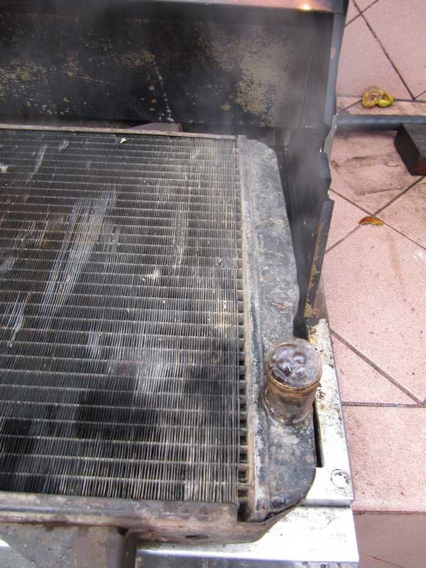
I tilted it a few times to get all the air bubbles out and boiled it for about half an hour. As it came up to temperature, I removed excess water with a turkey baster. Eventually, it reached the point where it simmered nicely without boiling over. After it cooled, I flushed it with more water; it seemed to flow well. Finally, I washed the outside with a pressure washer. There was a surprising amount of dirt stuck in the cooling fins; I suspect that many cooling problems in older cars are caused simply by built-up dirt in the fins.
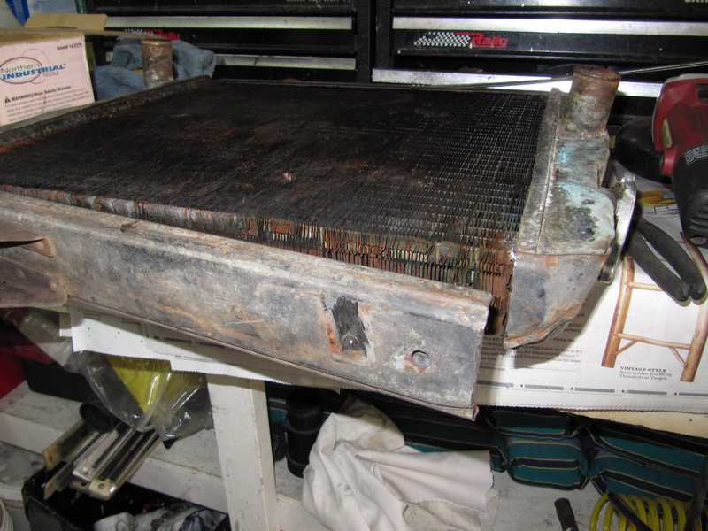
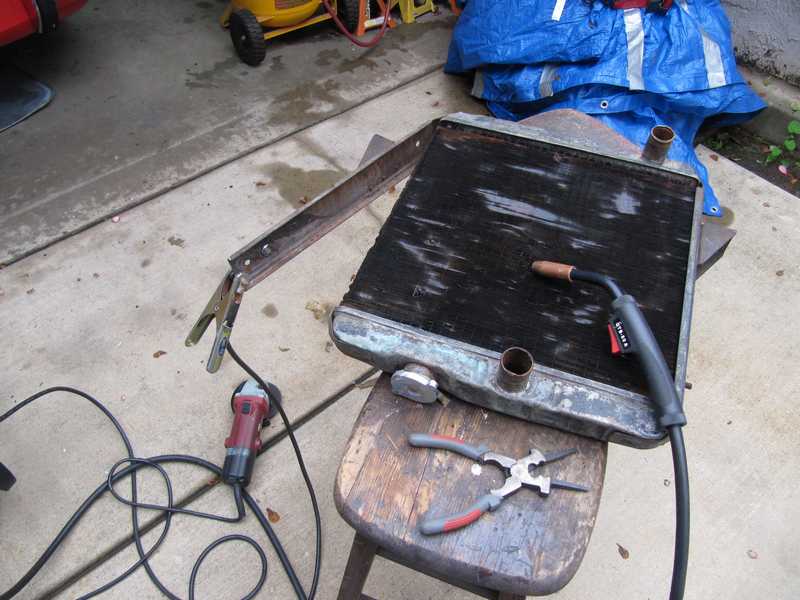
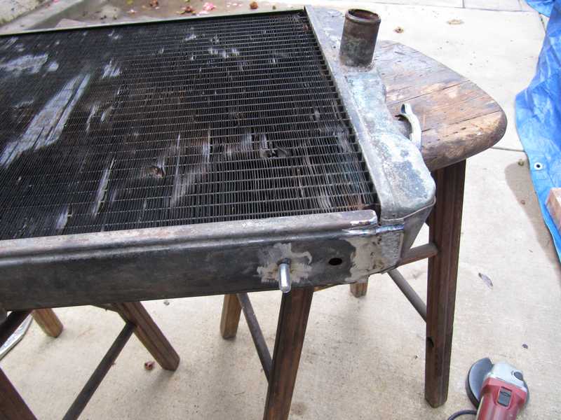
One of the mounting studs was broken off. I repaired it by first cutting it off flush, then cutting the side sheet metal at one end so I had access to the inner side. I drilled out the remains of the stud, using a piece of flat steel behind it to protect the radiator core. I tapped the hole, inserted a new stud, and welded it from the rear. Finally, I welded the sheet metal back together and ground it smooth.
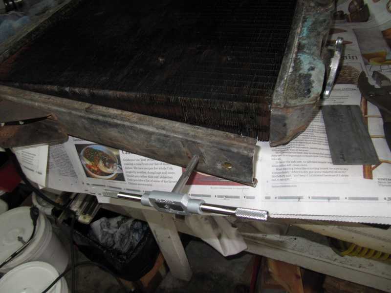
Many of the radiator fins were flattened; for best airflow, they had to be straightened. I bought a special tool to do that, but it turned out to be useless. Running a small screwdriver between them, although a little tedious, was the best way to straighten the fins.
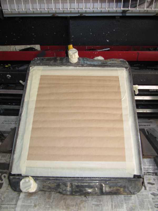
The semigloss Rustoleum paint I used for most of the black underhood items is good only to about 200F, which is marginal for a radiator. Instead, I painted it with black engine paint, which can handle a higher temperature. I sanded the radiator to remove rust and loose paint, masked it with conventional masking tape and brown paper, primed it, and painted it with a couple coats of the black topcoat.
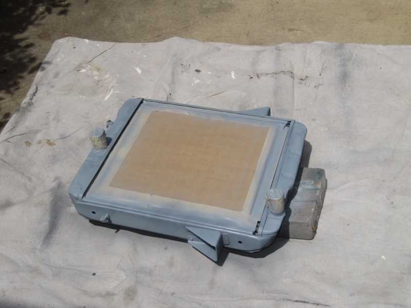
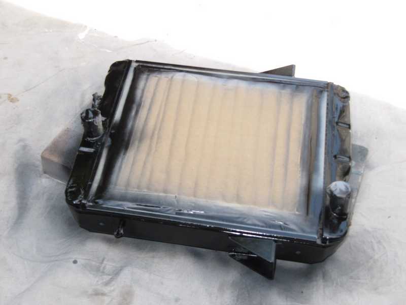
Below is the finished radiator. I didn't do anything to spruce up the cooling fins, as any kind of coating, especially paint, would compromise the heat dissipation. These little cars need all the cooling they can get.
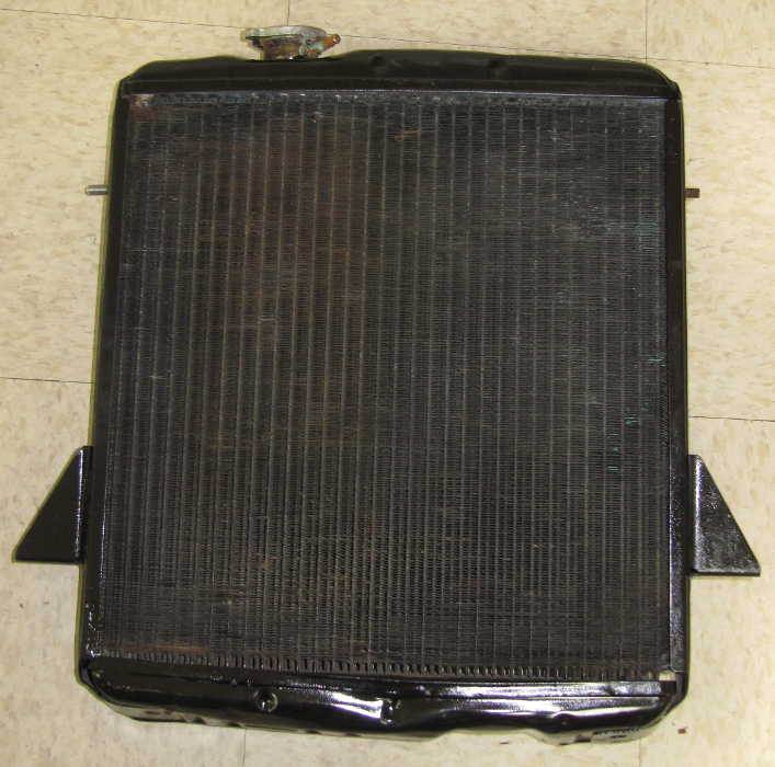
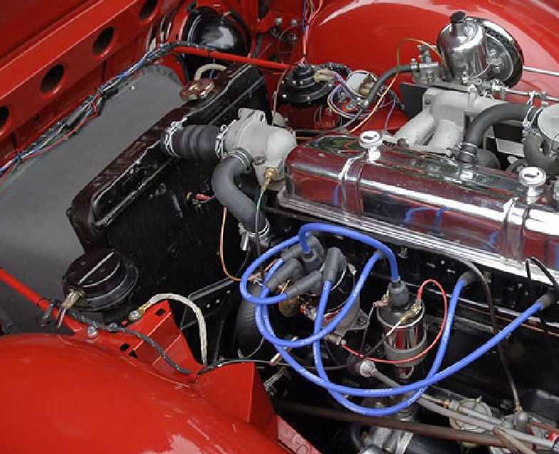
The radiator was stored a year and a half before I was ready to install it. At that point, I realized that something was wrong: the radiator's inlet port did not line up with the thermostat housing's outlet port, making it difficult to fill the cooling system completely. I had noticed this as I disassembled the car, of course, but at the time, it just didn't register as a problem. Below, the radiator as I received the car and a stock picture of a (very lovely) TR4A for comparison. You can see the problem.
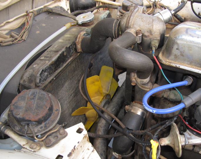
In the hope of discovering what I had, I searched on-line for pictures of radiators, but I could find nothing identical. Eventually, a denizen of the British Car Forum suggested that it was a modified TR6 radiator. I had noticed that it was the size of a TR6 radiator, but the ports were in the wrong places, so it seemed that it had to be something else. On close inspection, however, I could see the place on the upper tank where the TR6 port was patched. There was a similar patch on the lower tank, where the outlet was moved to the opposite side. It seemed clear that it was indeed a modified TR6 unit. The things people do to keep old cars running!

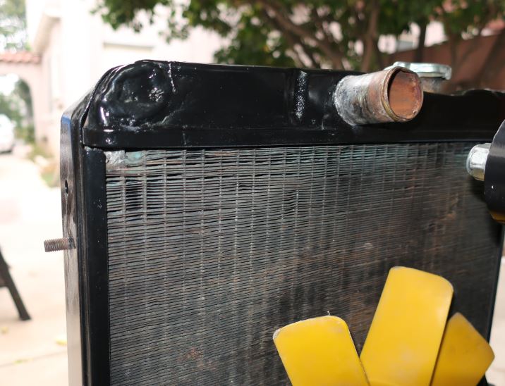
Finally (file this under adding insult to injury), the radiator leaked when under pressure. I discovered this on the initial engine start-up.
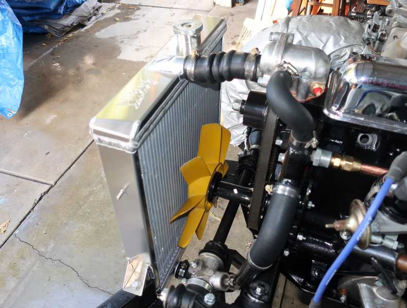
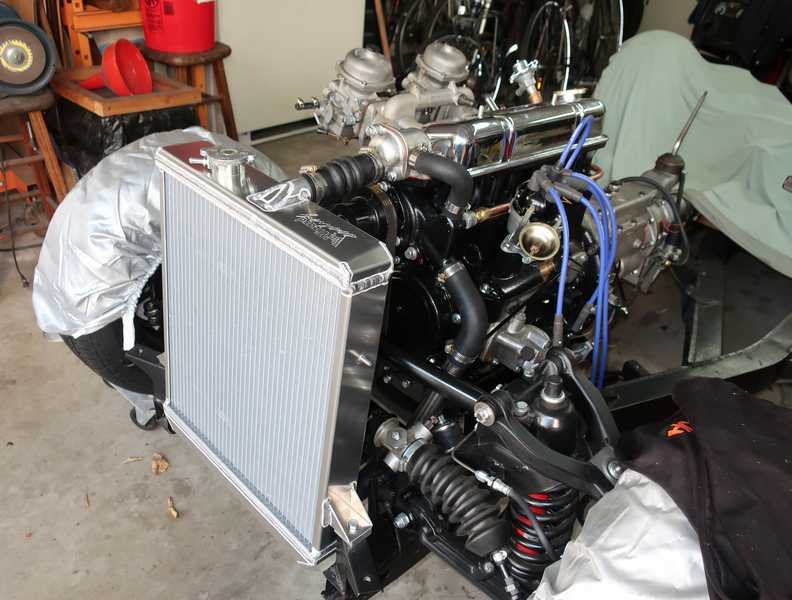
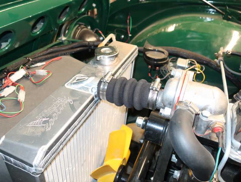
So, after all that work, I had to discard the radiator. I replaced it with an aluminum radiator from Wizard Cooling. Not cheap, but it should provide good engine cooling and be reliable. When first installed, however, its inlet seemed a little low, possibly because of the spacers I had to put under the engine mounts.
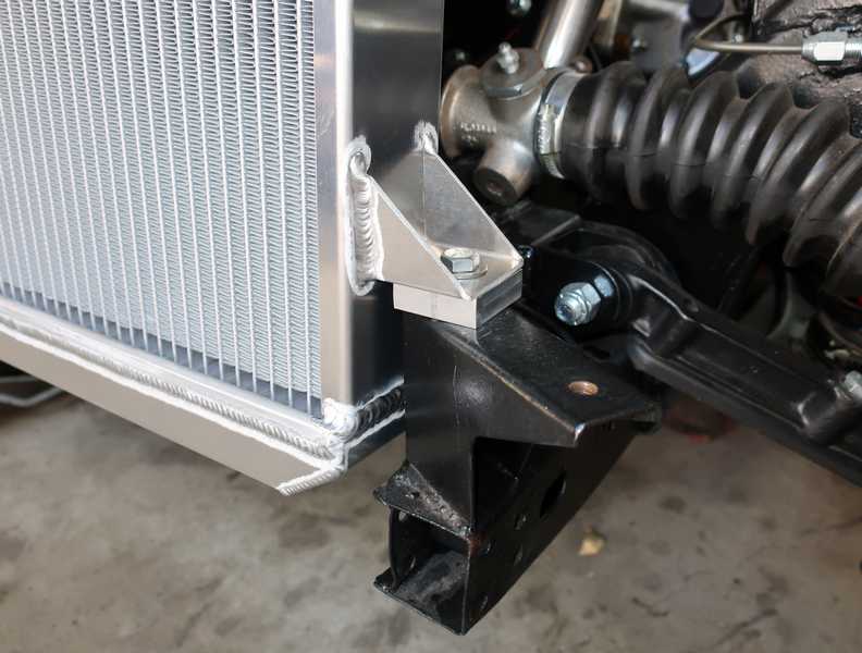
I machined a couple half-inch-thick aluminum blocks and placed one under each of the radiator's mounting feet. That leveled the radiator inlet nicely.
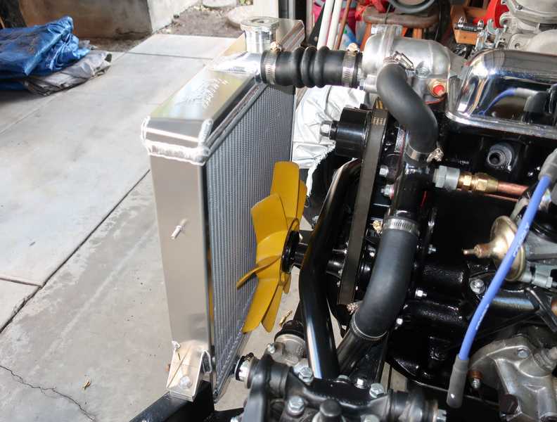
As well as being more reliable, the radiator looks really good. Too bad it's hidden away in the engine compartment!
Somewhat later, I installed a new air duct in front of the radiator; the old one was pretty beat up. The new one was difficult to install and didn't fit well (typical modern replacement part), but I still managed to get it mounted acceptably.
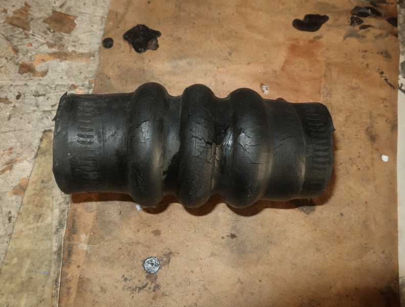
Three months after putting coolant into the engine, the top hose developed a pinhole leak. I had noticed that the rubber had started to crack, but I hoped that the cracking was just superficial. It wasn't. I replaced it with a higher-quality hose from The Roadster Factory.
I think it's outrageous that suppliers knowingly sell things that are not simply unreliable but certain to fail in short order. They must know how bad their stuff is, but they keep flogging it anyway. For the record, I bought this part from Victoria British, which recently became part of Moss Motors. They deserve each other.
Water Pump
The water pump showed, again, why I avoid new parts and restore existing ones whenever possible. I encountered a number of problems in installing the pump, all of which (I later learned) are well known.
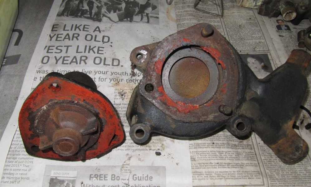
The original pump is shown below. For a couple of reasons, I decided not to use it. First, restoring the pump requires removing the impeller, which is almost impossible, as it is a very tight press fit and there isn't enough room to attach a puller. Second, the bellows seal between the impeller and bearing is difficult to find, and, when available, is half the price of a new pump. I'm told that other seals can be made to work, but I have no first-hand knowledge of that. Third, some newer pumps have an improved impeller, which provides increased coolant flow.
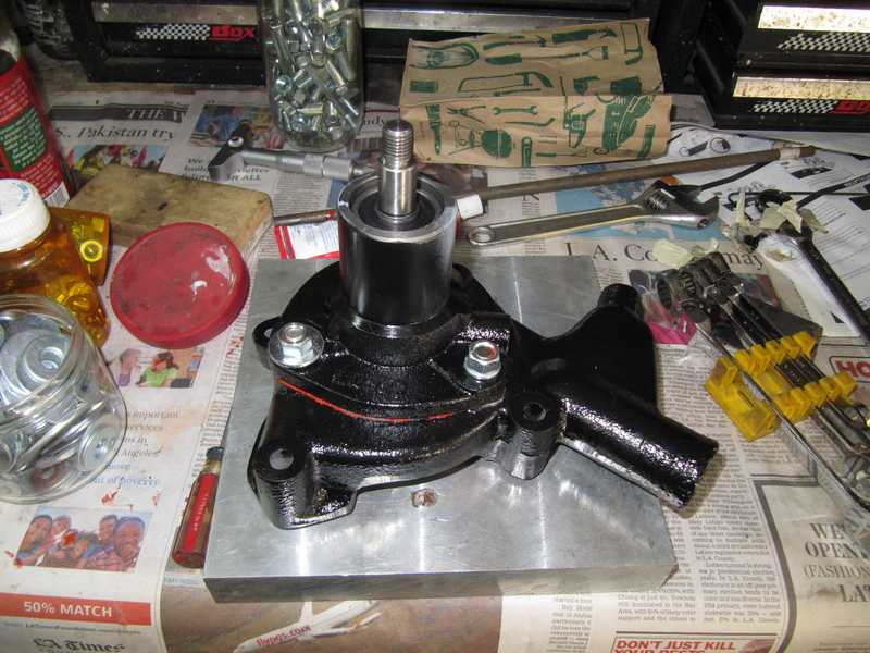
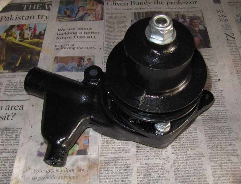
I obtained a new Lucas pump with the famous "five-blade" impeller. It was unpainted, so I painted it black for appearance and protection. The usual process: clean, prime, paint with engine paint, and dry it in the sun. I mounted it on the similarly restored body with a new gasket and sealer.
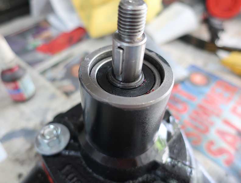
My first problem on reassembly was the Woodruff key in the pulley shaft. The pump included a 3 mm key (0.118 inch), while the slot in the pump shaft was 1/8 inch (0.125 inch), apparently sized for a no. 5 SAE key. The slot in the pulley, however, was a little less than 1/8 inch, so the key didn't fit well. It was not so small that I thought it was cut for 3 mm, but it still was several mils too narrow for the 1/8-inch key. Attempting to fit the pulley just pushed the key out of its slot. I had to grind the upper edge of the key a little to make it all fit together.
Below is the pump with the correct, no. 5 key in place.
Installing the pulley was tricky, as there was no way to see the key and to be sure it was aligned properly. When I finally got the pulley into place, I discovered that it rubbed on the body of the pump. I had to disassemble it (accompanied by some choice language) and grind down a couple high points on the pump body. Then, of course, repaint and reassemble.
The pulley's tight fit onto the pump shaft is important, as a loose pulley can eventually break the shaft. The pulley is large and heavy, and if the shaft were to break while the engine was turning fast, it could do a lot of damage. Especially to my expensive new aluminum radiator.
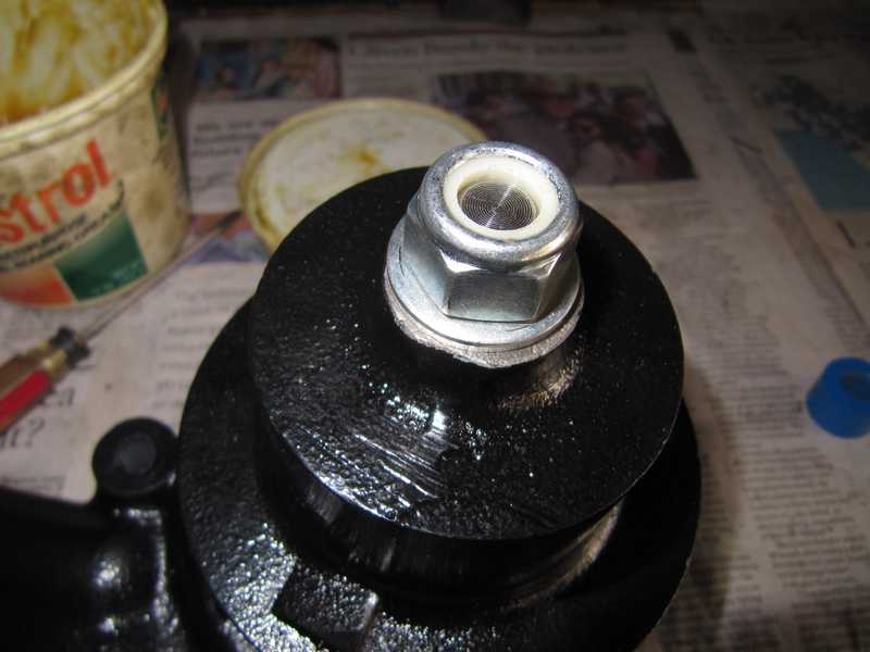
The half-inch nyloc nut provided with the pump was much larger than the original, and it didn't thread onto the shaft far enough to allow the nylon portion to engage the threads. I found a smaller, thinner washer and drilled it out to 1/2 inch. That allowed the nut to thread onto the shaft properly. It probably doesn't really need a washer, but I installed one, if only for the general principle that nuts should have washers.
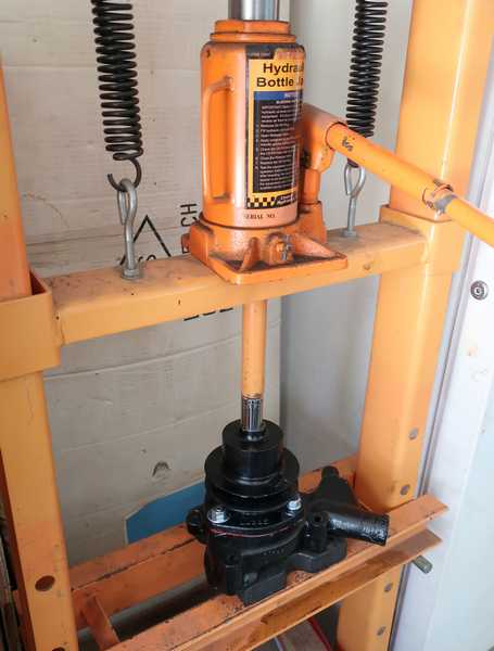
Tightening the nut was a pain, as there was no easy way to hold the pulley firmly as the nut was tightened. As in other cases like this, I used an impact wrench to tighten the nut while holding the pulley with the drive belt wrapped tightly around it. The restored pump looked good, and I was confident that it would work well. But it required far more work and time than it should have.
Later Note (late 2024)
It appears that the pump with the five-blade impeller is now being sold with an included pulley. It is actually possible that the included pulley fits the pump; if so, many of the problems described here may no longer exist. We can hope, I suppose.
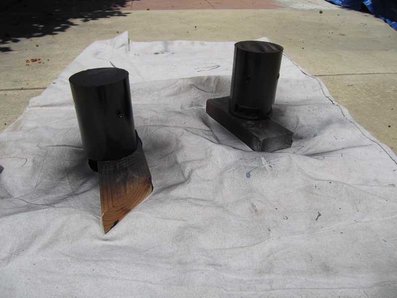
Thermostat and Housing
The thermostat on the right is an original one; the one on the left is a modern thermostat, sold as a replacement. The old one clearly is dead, as it is open at room temperature.
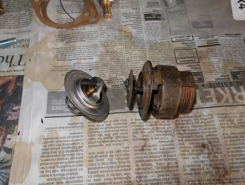
The modern thermostat is not a perfect replacement. That wide band on the old one opens the radiator bypass when the engine is cold, and it closes the bypass when the engine is warm and the thermostat is open. This functionality is common in British cars. There is no equivalent structure on the modern thermostat, however, so an orifice in the bypass line allows coolant to bypass the radiator when the thermostat is closed. When the car is warm, though, the orifice is not closed, so some of the coolant inevitably bypasses the radiator. You can see the orifice, in pump body, in the right picture below. Presumably, that's adequate; we'll find out, for sure.
The new temperature sensor I bought seemed very different from the one that was on the car. I measured both cold: the new one was 640 ohms, and the old one 230. Either the new one was wrong, I figured, or the old one defective. To determine which one to use, I calibrated both in a hot water bath, with a 10V power supply and the car's temperature gauge. Both worked acceptably, but the old one reached the overheating range (the red region on the gauge) at only about 195F, which seemed too low. The new one reached it at 205 degrees, which was more reasonable, so I decided to use that one.
Exhaust System
Manifold Restoration
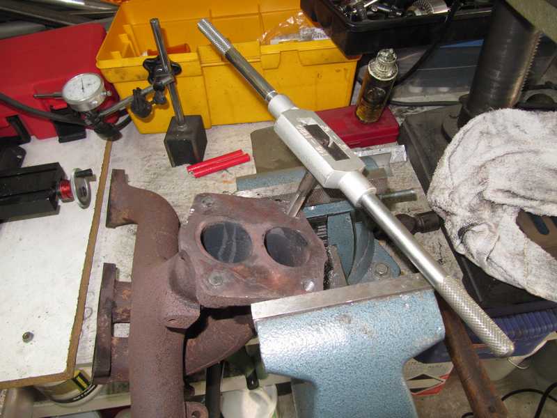
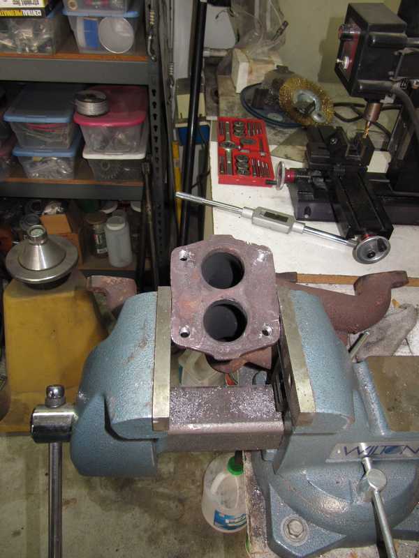
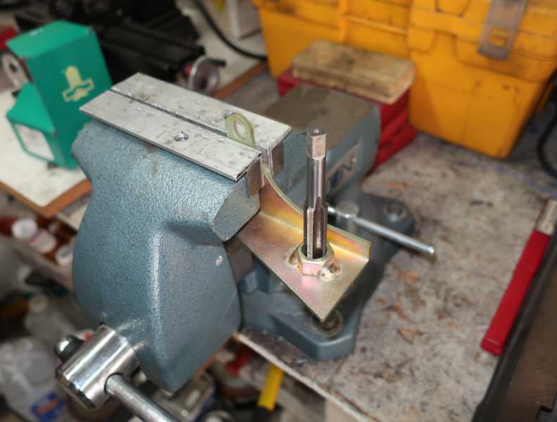
The studs at the output end of the exhaust manifold were badly rusted and had to be replaced, but they were rust-bonded into the manifold flange. I tried the usual tricks for removing rusted studs, but nothing worked. I welded nuts onto the studs and gave them a long soak in "weasel pee" (50-50 mix of acetone and automatic transmission fluid), but when I tried to remove them, they broke under relatively low force. They seemed to have been softened by repeated exposure to high temperatures. It was clear that I'd have to drill them out.
The trick to drilling out a broken stud or bolt is to make a guide hole precisely in the center of the stud and to drill it out in steps. Centering the hole is easier if the manifold can be mounted in a drill press, but its size and shape usually preclude that, and drilling by hand is the only option. Precise centering requires great care, as the drill tends to wander.
I first ground the end of the stud flat, center-punched it, and used a spotting drill to enlarge the dimple. I then drilled a 1/8-inch guide hole in the 3/8-inch stud, enlarged the hole to 1/4 inch with a carbide drill, and drilled it out again to 5/16 inch. That's as far as I could go without risking damage to the threads.
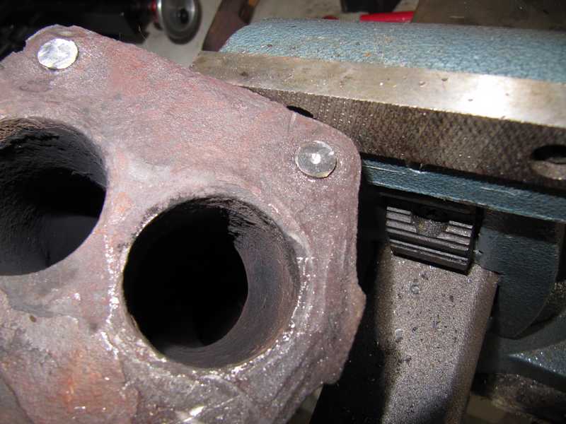
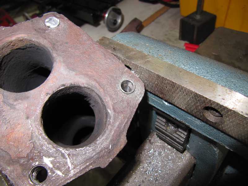
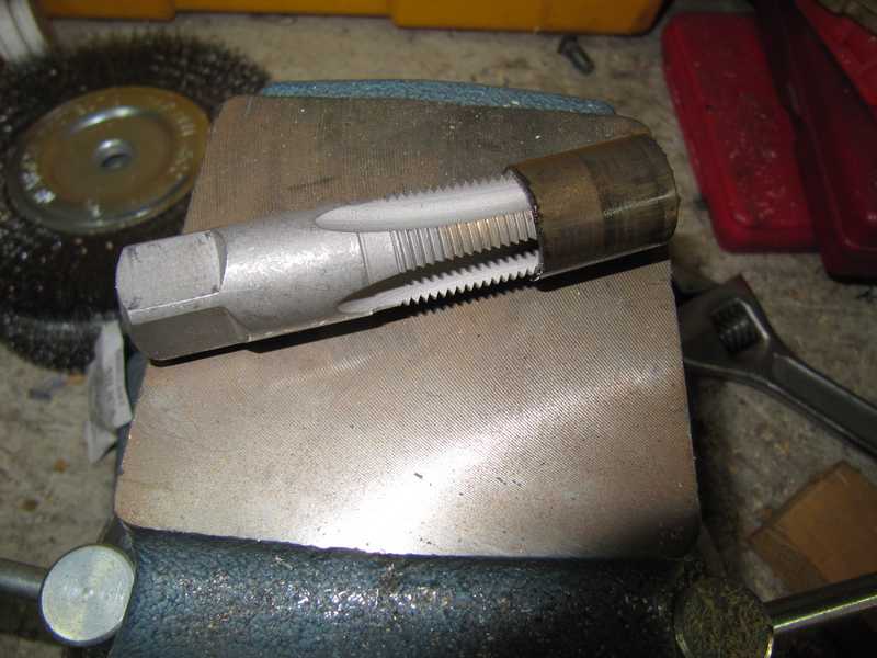
At that point, there was very little metal in the hole, so it was easy to collapse it inward with a chisel. Even then, some of the threads were bonded so tightly by rust that I had to use a tap to remove them.
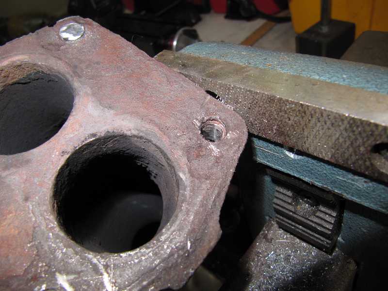
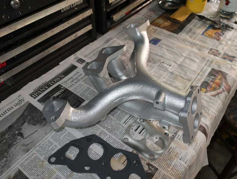
Below is the flange with the restored stud holes. Some bits of the gasket's metal surface were still rust-bonded to the flange. I had to remove them before the manifold was ready for refinishing.
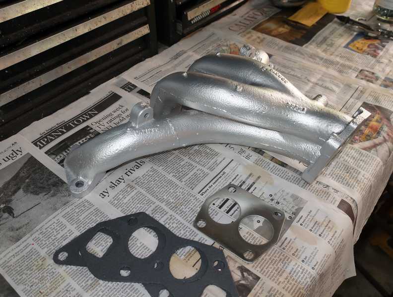
Unless the manifold has a high-temperature coating, it will rust in short order. That's unacceptable, so I sent the manifold to Jet Hot for ceramic coating. They were pleasant to work with: good work, transparent pricing, quick turn around, delivery when promised. I think it looks a lot nicer now, and it should stay that way.
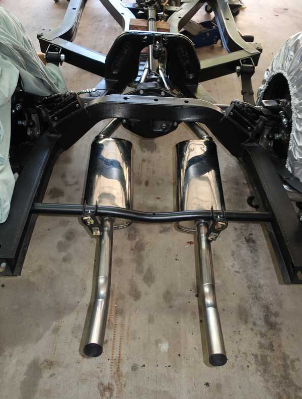
Exhaust System Installation
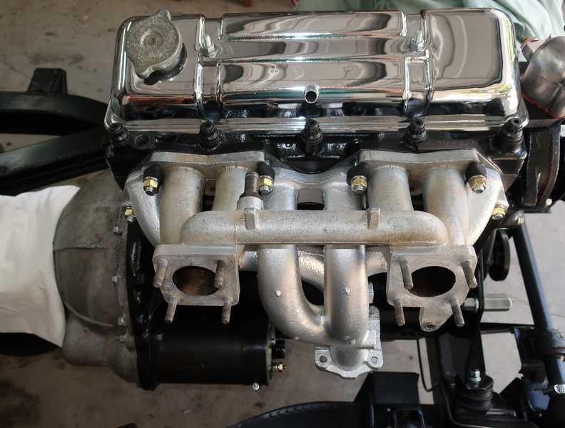
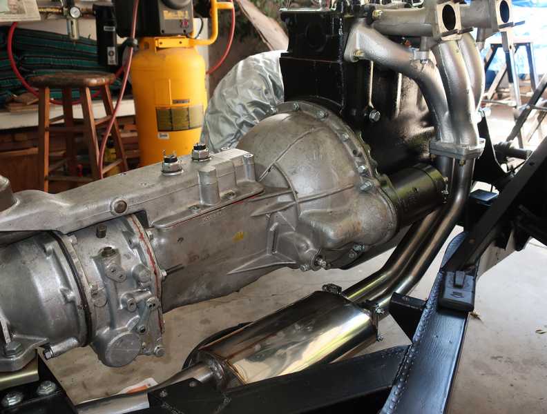
I mounted the exhaust and input manifolds onto the engine with hardware made of 316 stainless steel, which is highly corrosion-resistant, and brass. The manifold "T" clamps were painted with high-temperature exhaust paint. I prepared them carefully and heat-treated them per the instructions on the paint can. We'll see if it lasts.
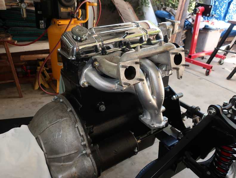
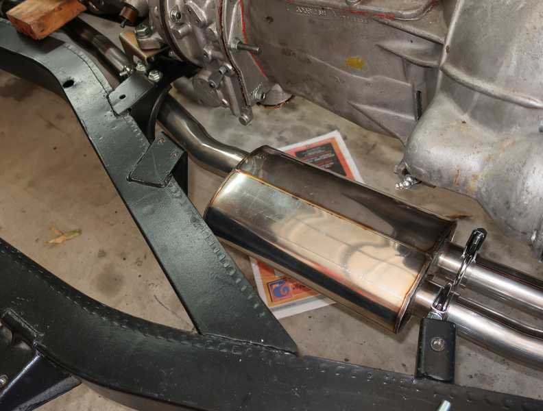
After looking into a number of options, I bought a Bell stainless-steel exhaust system. I would have been happy with a less-expensive galvanized exhaust system, but they are not available for the TR4A any more. I also considered making my own system, but I don't have the equipment to bend exhaust tubing, and I wouldn't know if the muffler I bought would have a reasonable sound and would not be too loud.
The Bell system went together fairly easily; the only problem was that the outputs of the Y tube were not really parallel. I was able to solve the problem with a little muscle, but that really shouldn't have been necessary.
I used 316 stainless steel studs with 316 lockwashers and brass nuts to connect the manifold and double-pipe flanges.
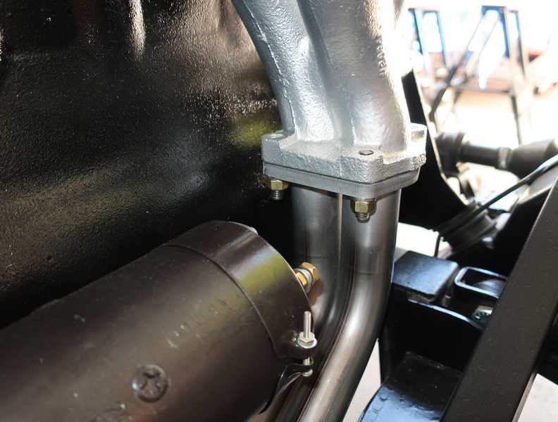
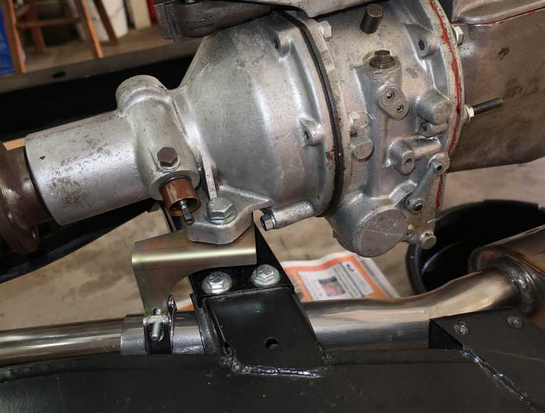
Again, I bought replacement parts that I could have made myself, and I regretted it. I bought the front hanger bracket and clamp from one of the Usual Suspects, because they were not expensive and I just didn't feel like spending the extra time to fabricate them. The bracket consisted of a piece of bent metal with a nut welded to it. You'd think that no one could screw up something so simple; but then, you'd be wrong. I don't know how the nut's threads got as bunged up as they were, but, whatever the story, I had to run a tap through it to fix its threads. Not a big deal, but repairing it really should not have been necessary. Then, the screw on the clamp required a 10mm metric wrench. This is a BRITISH CAR, goddammit! It should require only English-sized tools!
I had planned to make my own rear hangers from pieces of fabric-reinforced rubber, like the original ones. The material was hard to find, however, and when I found some, it was surprisingly expensive. I gave in and ordered the parts, as they were not expensive. You might think that the hangers, as they're simple enough, would be made the same way as the originals; but then, you'd be wrong. They were just simple, unreinforced, rubber blocks. Well, I can revisit the issue when they break, which probably will be fairly soon.
Except for the clamp near the hanger, I used ordinary, "chromed" (probably really nickel-plated) C-clamps from McMaster-Carr. I had at least that much sense.
Crankcase Breather
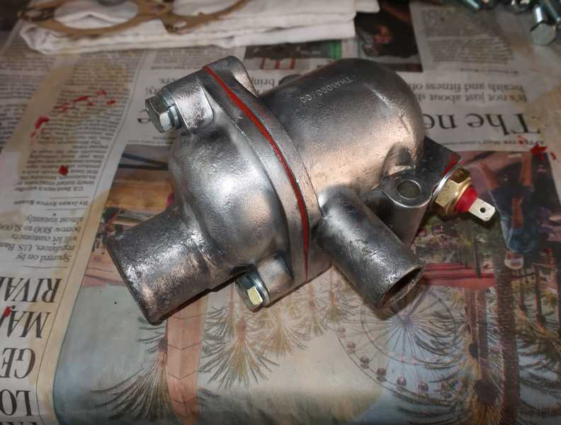
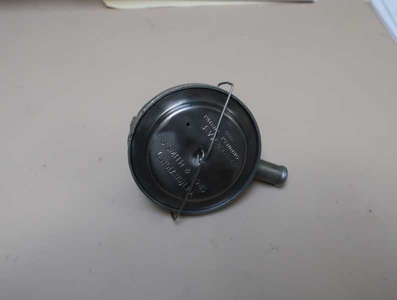
AKA PCV valve. A PCV for any other car costs $5, but this one, because it's a complicated, overdesigned part, costs $70. Makes it worth the trouble to fix the old one.
Below is the old breather. Its rubber diaphragm had hardened and split, so the valve, as it stood, was useless.
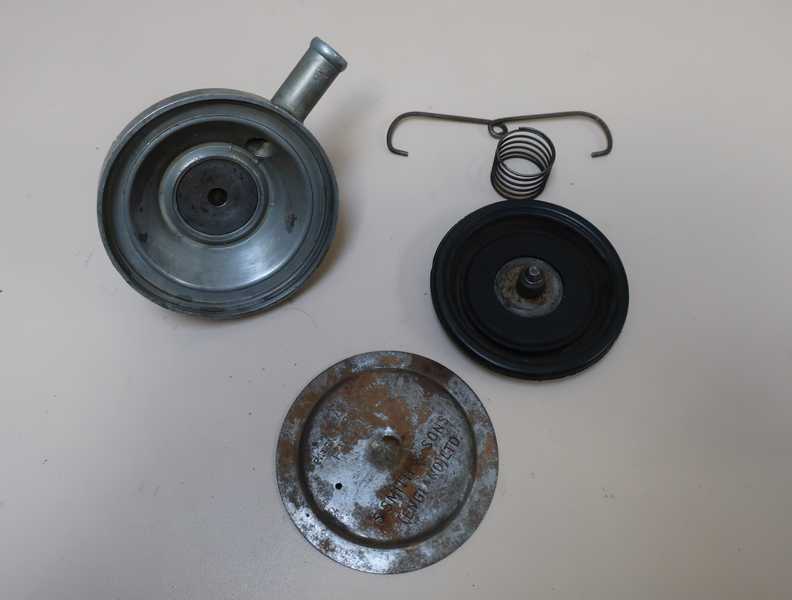
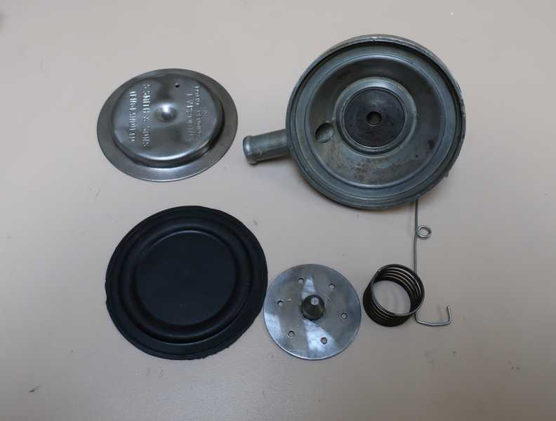
Replacement diaphragms are available, but they are designed for a later valve; exact replacements for the old ones are not available. Still, I decided that I could make a new diaphragm work. The only difference between the new and old diaphragms is that the valve pin, on the old ones, is embedded in the diaphragm, but in the new ones, it's free floating. There seems to be little or no difference between the diameters of the pins' mounting plates in the two models.
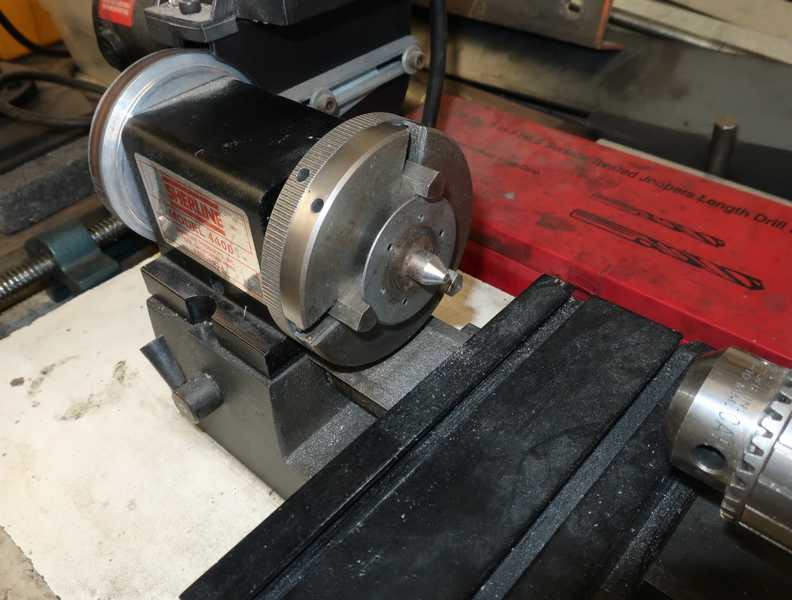
First, I removed the valve pin from the old diaphragm and, since the surface was worn, I cut a new surface on it.
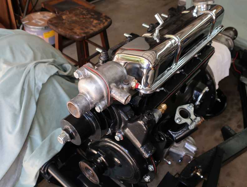
I also made a new, stainless steel cover-retaining spring; the old one was pretty rusty. I put it all together, and it passed the suck test: if you suck on a port, with the other one sealed off, the valve closes and doesn't leak. I think it should be OK.
I had already bought a new one, so I used it and kept this one as a spare. The new ones are a little different; I think they are really for the TR6. Conversely, this type of breather is used on a number of British cars. I understand, though, that it's not a very critical component; I've even seen TR4As using the cylindrical breathers from American cars.
The whole matter of crankcase ventilation is an interesting one, and it's worth a little trouble to do a search and find out all about it. Here is a good place to start.
I later noticed that the hose from the breather valve to the manifold collapsed under engine vacuum; yet another crapola part from the Usual Suspects. I reinforced it by inserting a spring into the hose.
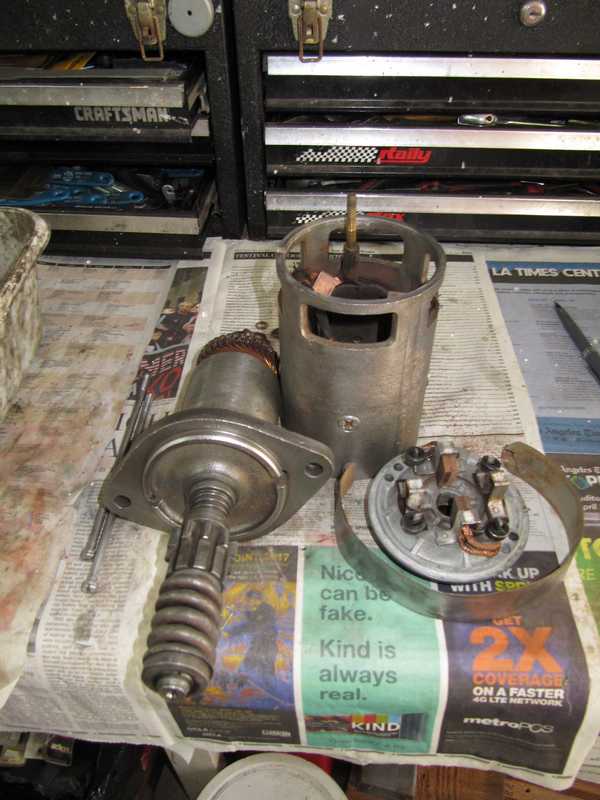
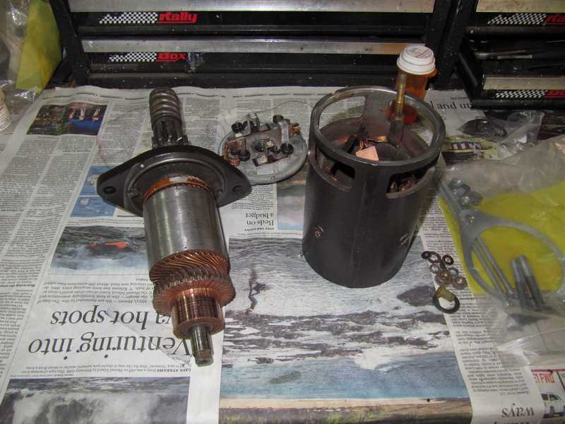
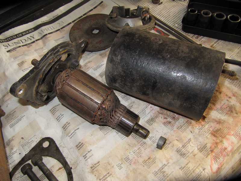
Starter
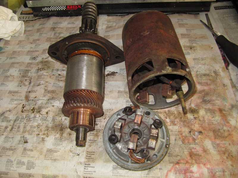
The starter looked old and rusty, but internally it was in good condition. The surfaces that rode on the bronze bearings were fine, as were the windings and commutators. This made it sensible to reuse it.
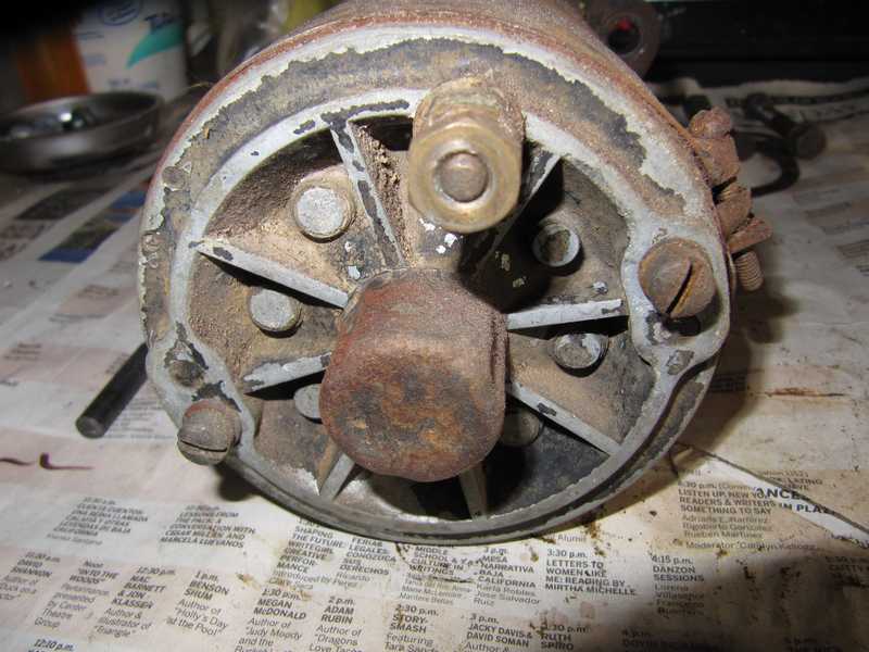
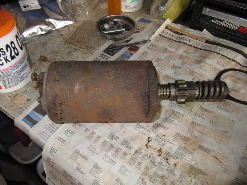
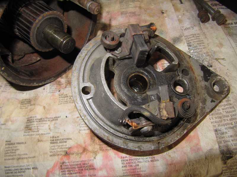
The starter's brushes had plenty of life left. They rarely need replacement, as they are copper, not graphite, and starters just don't get much use. Their wiring is riveted, an indication that the brushes are expected to last as long as the rest of the starter. The bronze bearings seemed smooth, so I didn't replace them. There was little to do beyond wire-brushing off the rust and repainting.
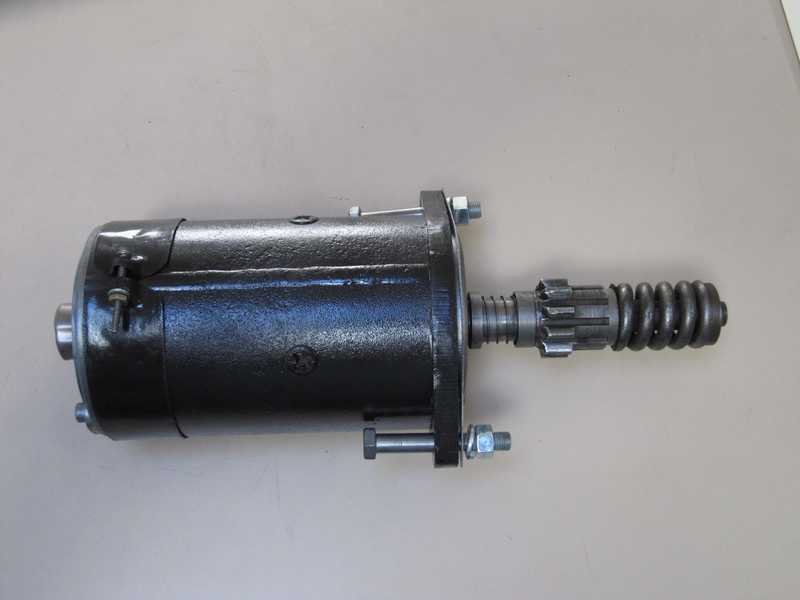
I replated some of the starter's parts, including the mounting bolts, as I don't have 3/8" UNF bolts of the correct length in my stores, and UNF bolts are surprisingly difficult to source locally. I painted the starter's body and the outside part of the mounting flange, but not the face that mates with the engine. (More pictures below, in the Generator section.) At some point I may replace it with a gear-reduction starter, but for now, it looks good and should work well.
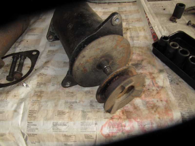
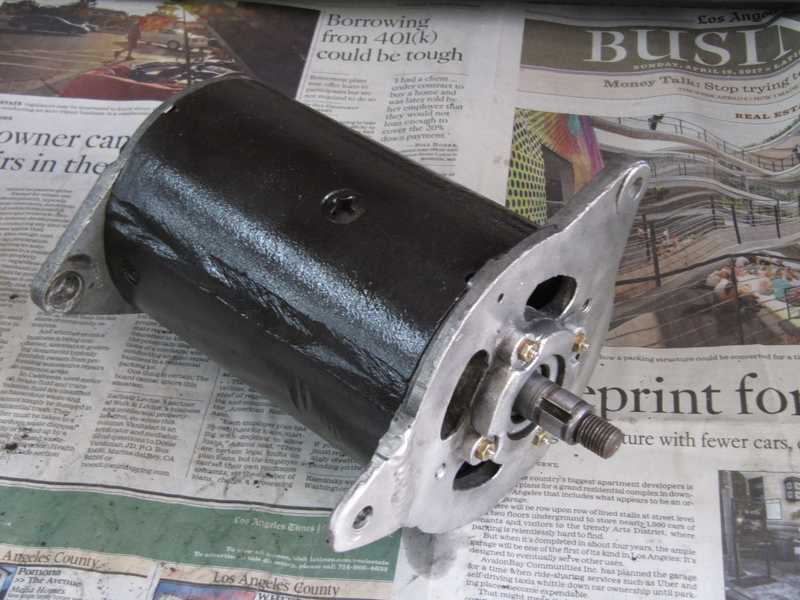
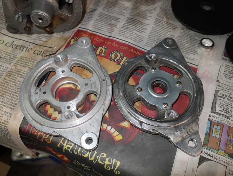
Generator
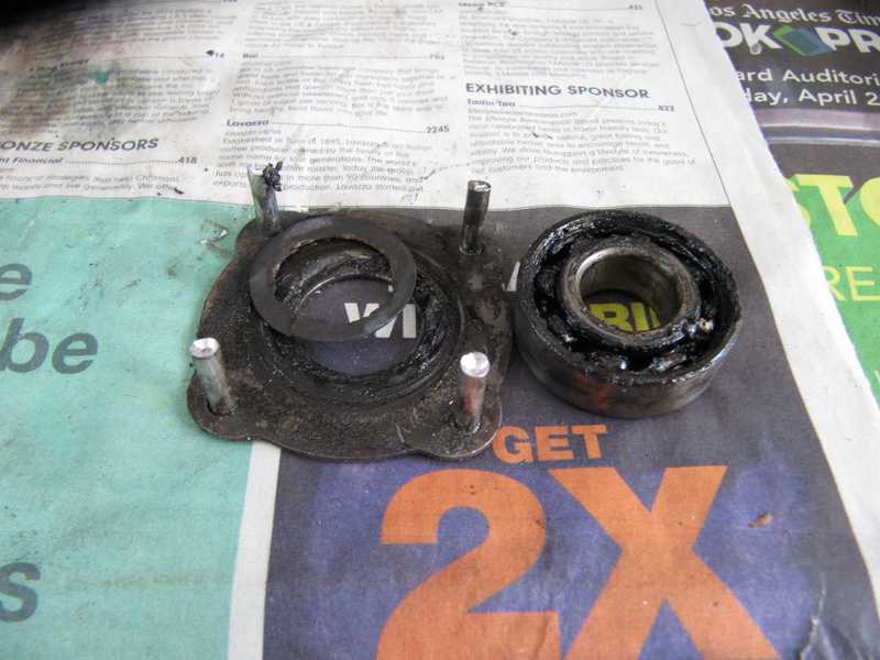
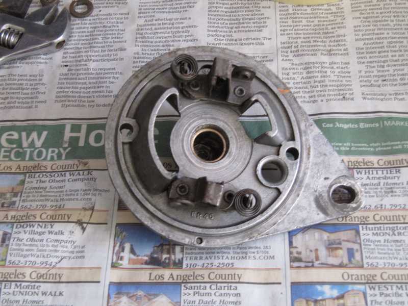
The generator was due for some attention, but in terms of the things that really matter, it wasn't half bad. The commutator looked fine, as did the bronze bearing and brushes. The output shaft bearing was smooth, but it had lost one of its covers and its grease was black and dirty. The wrappings of the field coils were shabby, but that really doesn't matter much as long as the wiring and insulation are good. The housing needed a coat of paint.
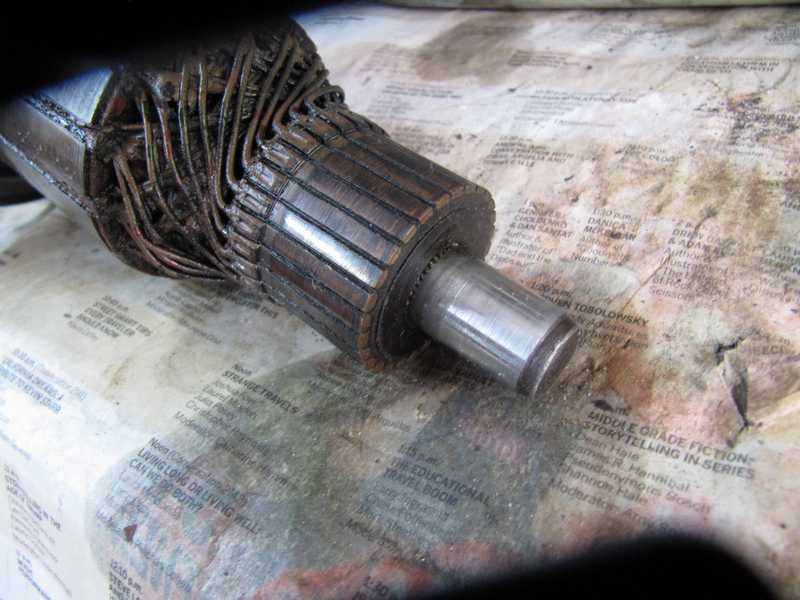
Below is a close-up of the commutator. The undercuts were still deep and there was little wear on the contacts. The shaft that rides in the bronze bearing was smooth and free of scoring or other wear. The dark color of the copper commutator segments is caused by the graphite brushes and doesn't do any harm. In the past, I have resleeved bearing surfaces and turned down commutators to restore them, but that didn't appear necessary here.
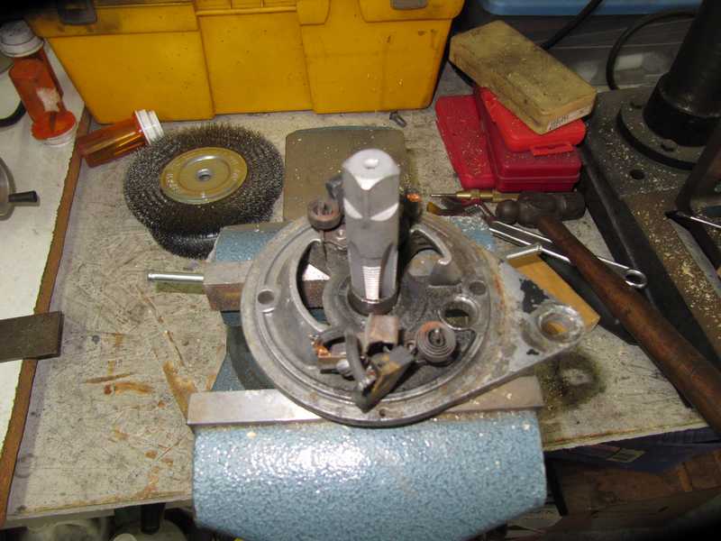
To maximize the generator's service life, I replaced both bearings and the brushes. My trick for removing the sintered bronze bearing is to use a pipe tap to grab it, then either yank it out or, in this case, tap it out with a drift.
The output shaft bearing was grungy; although it still turned smoothly, one side plate had come off and it was showing its age. I replaced it. The bearing was held in place by a riveted retaining plate. I drilled out the rivets and replaced them with screws.
Below are some replated parts from both the starter and the generator. The distributor clamp, which I replated at the same time, is also shown in the picture. I repainted a number of the pieces of both units; the housings are shown below. I also fixed the damaged wrappings of the generator's field coils by painting them with varnish. The varnish holds the old wrappings together and helps to protect and insulate the wiring.
The endplates of the generator are aluminum and will not rust, so I saw no need to paint them. The front plate has an obvious repair, done competently. That's a much nicer aluminum weld than I could do. Below are pictures of the plates with the new bearings installed.
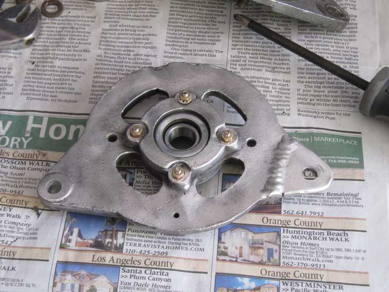
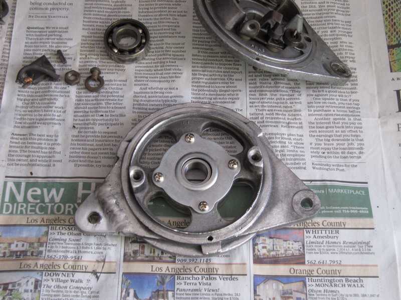
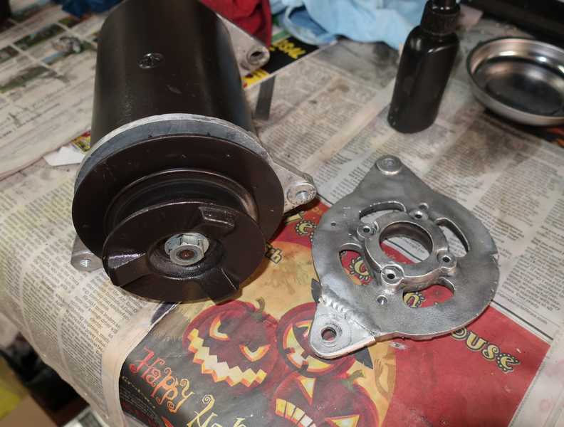
With a couple long screws, the generator was back together. Installing the back plate of a Lucas generator can be tricky, as it is sometimes difficult to keep the brushes retracted while sliding the plate into place. The shop manual, however, shows a simple way to circumvent that problem. I trimmed the ends of the screws that replaced the rivets for the output shaft bearing, so the fan cleared them easily. The final picture shows the generator with the pulley and fan reinstalled.
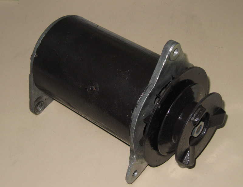
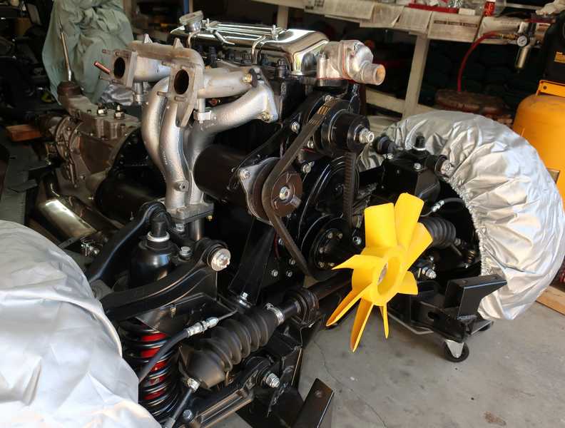
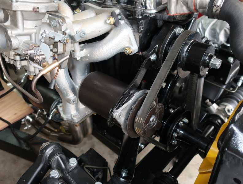
Many months after restoring it, the generator was installed on the rebuilt engine.
After installing the generator, I noticed that the nicely welded mounting tab had cracked along the outer side of the weld. It might have been my fault, as it's easy to put a lot of force on the tab while mounting the rather heavy and awkward generator onto the car. Indeed, that might have been what broke the mount in the first place. Whatever the cause, this obviously had to be fixed.
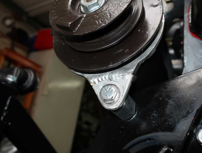
Gotta love eBay! I was able to buy a new generator front plate for eight bucks, plus shipping. It was a simple matter to remove the old plate, switch the bearing, and install the new one.
The generator, with the new plate, was soon back on the engine. I was more careful installing it this time.
Oil Filter
My engine had an adapter for a spin-on oil filter, a worthwhile upgrade. That adapter does not modify the way the oil circulates in the filter, however, so the following description is valid for either this arrangement or the original one (which used a cartridge filter in a housing).
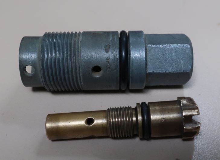
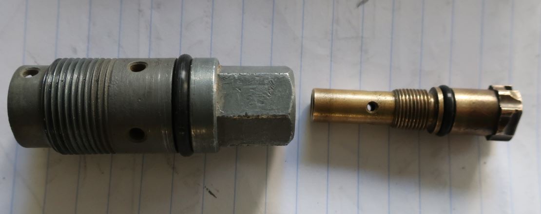
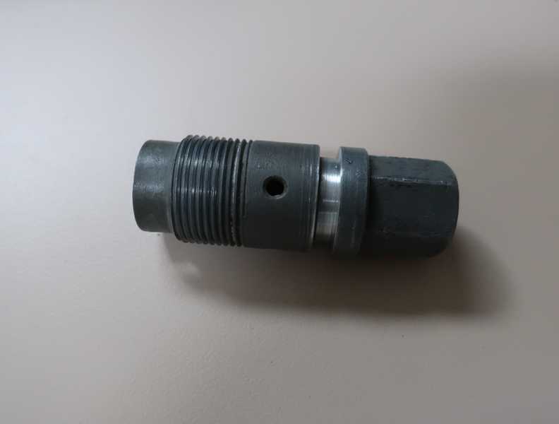
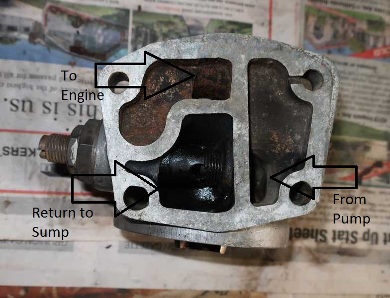
Oil is pumped from the sump to the filter. As with all modern oil filters, the oil flows through the filter from the outside toward its center; it then flows into the oil gallery, from which it is distributed to all the bearings. The filter mount includes a ball-and-spring relief valve, visible in the area marked Return to Sump. If the oil-pump pressure exceeds the valve setting, the valve opens, allowing oil to return to the sump. The valve's pressure setting is adjustable; the adjuster is on the left in the second picture below. It simply adjusts the force on the relief-valve's spring.
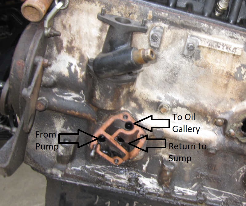
The oil-filter mount has a second relief valve, not visible in the picture, which has a much lower release pressure and is not adjustable. It allows oil to bypass the filter if the filter gets plugged; better to have dirty oil than no oil at all. Almost all modern filters include a relief valve, so that function is probably not necessary when a spin-on filter is used.
The oil pressure gauge is connected to the filter mount in an odd way. There is a notch in the mount between the input area and one mounting hole, visible in the top right of the mount, allowing oil to pass around the mounting stud. The line to the oil gauge is connected to that stud through a banjo fitting. Thus, the gauge reads pump output pressure, not oil-gallery pressure, as one might expect. The difference is the pressure drop in the filter, which, in any case, is probably pretty low.
The car had a Fram PH3600 filter when I received it. I'm not thrilled with Fram's quality, so I bought a Wix filter (no. 51516) for the rebuilt engine. It's much higher quality and even looks better.
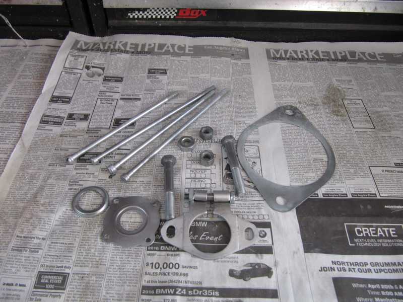
Miscellaneous External Bits
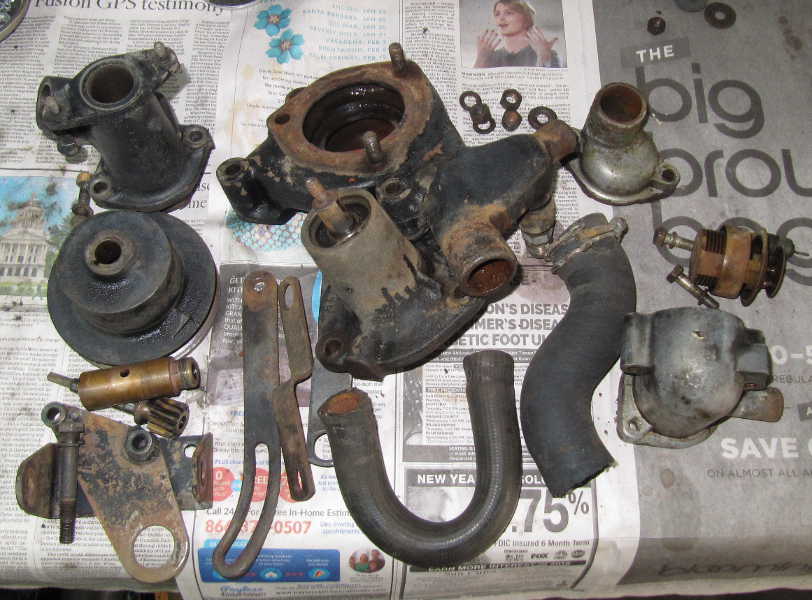
Below is a miscellany of external parts. The painted parts were restored in the usual way: solvent wash, detergent wash, rotary wire brush, prime, and paint. Most of the parts shown below are for the cooling system: water pump, radiator supports, and thermostat housing. The distributor pedestal is also shown, along with the tach drive.
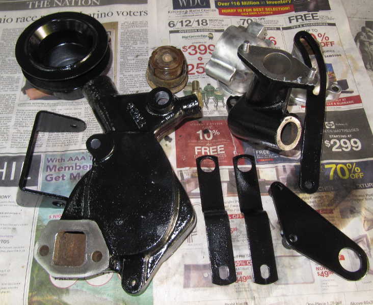
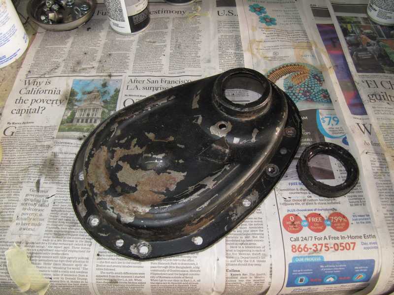
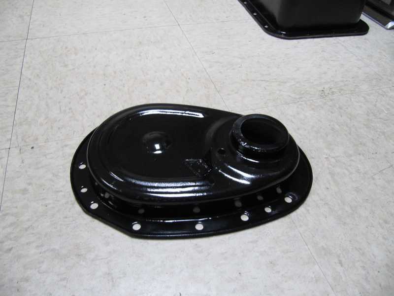
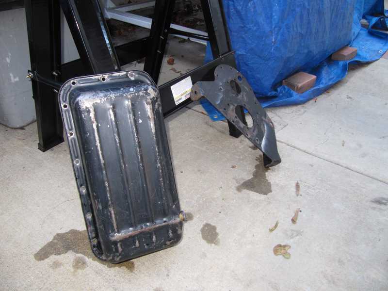
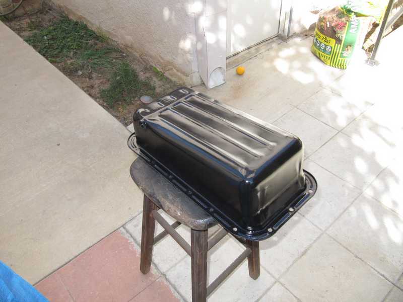
The oil pan contained a layer of sludge. Cleaning it was not fun, but after a couple solvent and detergent washes, it was no longer greasy. After that, I removed the paint, then primed and painted its outside only, of course. I also cleaned and painted the front engine plate but masked off the part under the timing cover. I didn't want paint there, as it could come loose after prolonged exposure to hot oil.
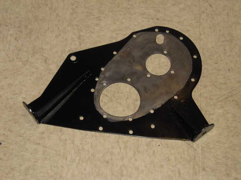
The timing cover was treated similarly. Its inside also was not painted