![]()
Interior Restoration
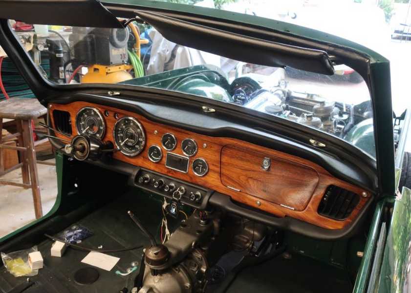
The interior wasn't too bad, but still not quite good enough. I replaced most of the interior parts, including the dashboard pads, carpets, seat covers, panels, and so on. Many parts, such as the dashboard and instruments, fortunately were restorable. The wood dash itself looked good; it wasn't the handsome walnut dashboard of the original TR4A, but I kept it anyway. Interior restoration is slow and laborious, but rewarding if done well.
Click on any picture to see a larger version in a new window.
Contents
- Heater
- Steering Wheel
- Seat Slides
- Handbrake Lever
- Dashboard
- Steering Column Installation
- Cables
- Instruments
- Assembling the Dashboard
- Sun Visors
- Shifter Console
- Interior Fittings
- Panels and Associated Trim
- Carpet Installation
- Seat Restoration
- Soft Top
Heater
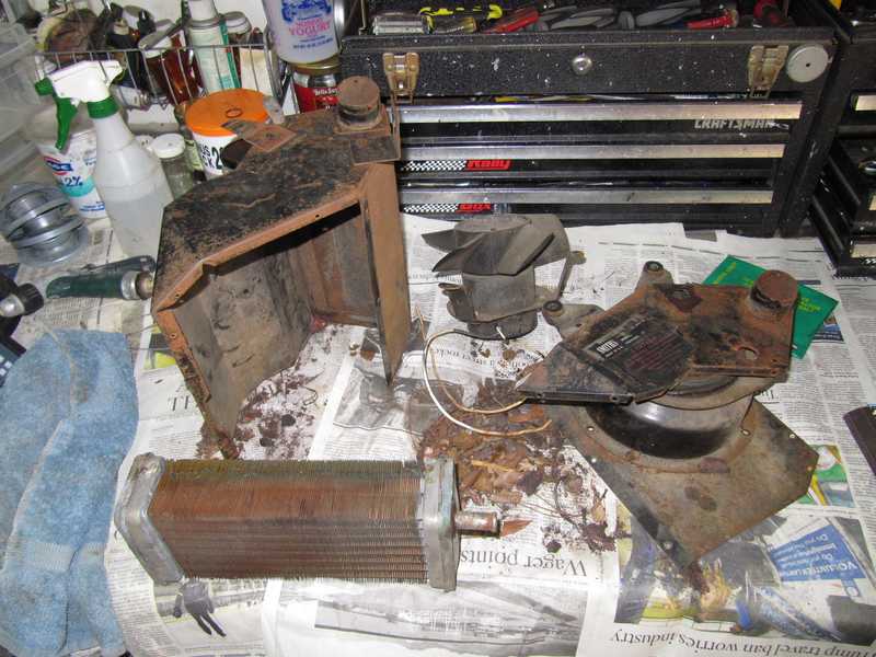
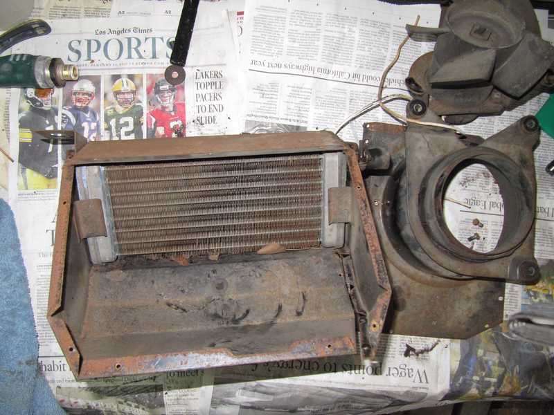
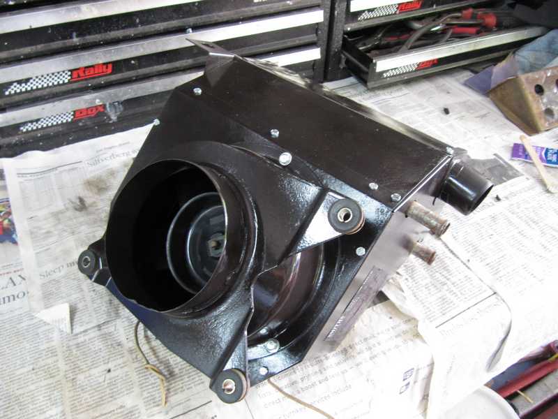
The heater needed only clean-up and repainting. It contained a lot of dirt and leaves, and the housing had a fair amount of nonfatal rust.
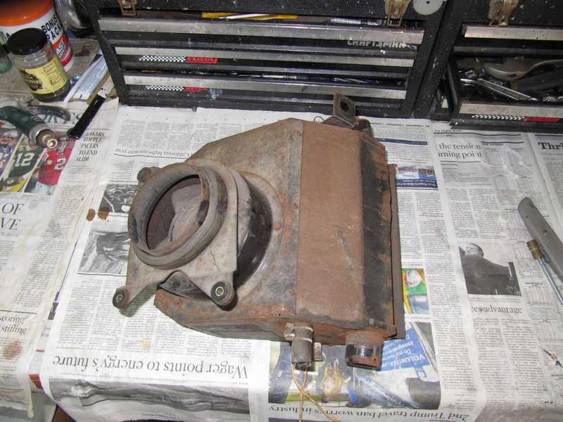
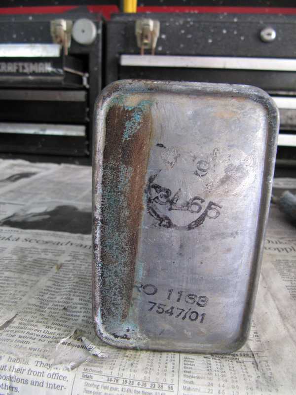
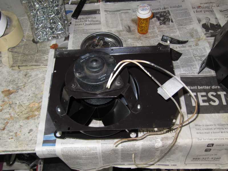
The heater came apart easily; just a few screws. Its interior wasn't bad at all. I washed the pieces in detergent and, when it had dried, sanded off the rust. The heater core looked good. Interestingly, it had a date stamped on it, 3/65. I tested the fan motor; it draws 3.9 amps at 12.6 volts, in case you were wondering. It also had a date marking, 4/65. That fits.
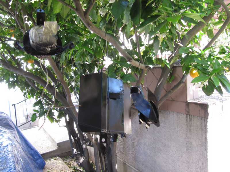
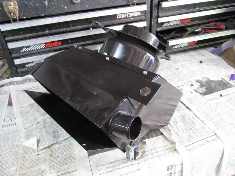
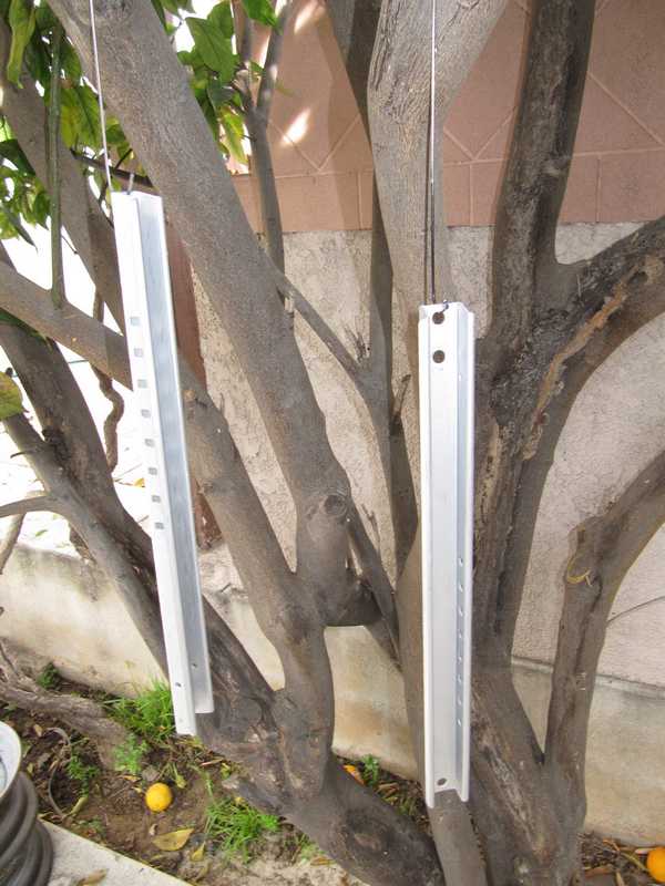
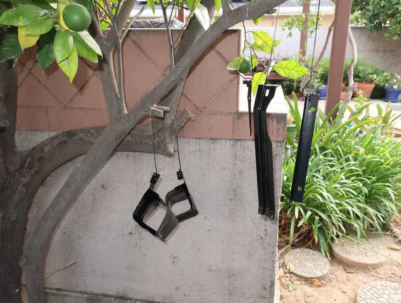
I then masked, primed, and painted the pieces and hung them from the orange tree to dry. To harden the paint, I set them on the warm patio, in the sun.

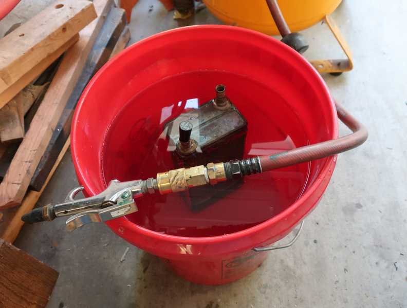
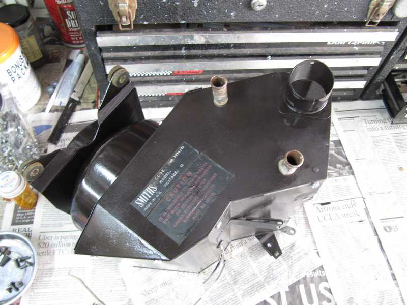
It was important to be sure that the heater core was leak-free, as any leakage would make a mess of my nice, new interior. I leak-checked the core by immersing it in a bucket of water and pressurizing it to 10 PSI with air. No bubbles.
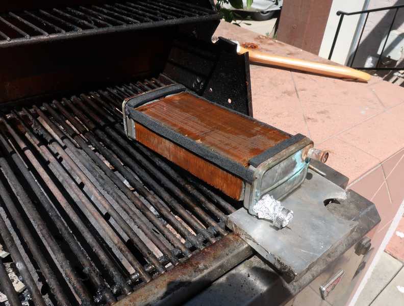
Finally, to clean its interior, I filled the core with radiator cleaner and boiled it on the barbecue grill for a half hour. Even though water had flowed through it freely, I still got a lot of gunk out of it.
The heater, with new hardware, went back together easily. The tag on the wire identified the (+) terminal.
The completed heater. It should be good for another 50 years!
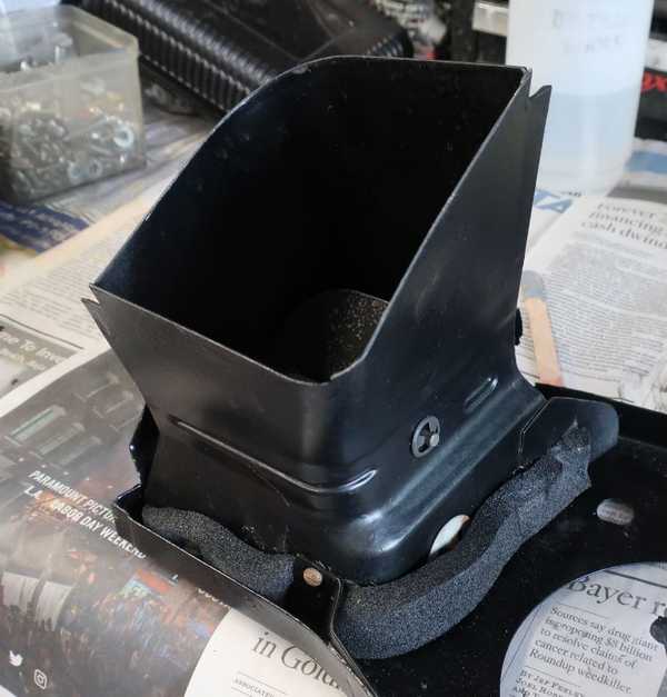
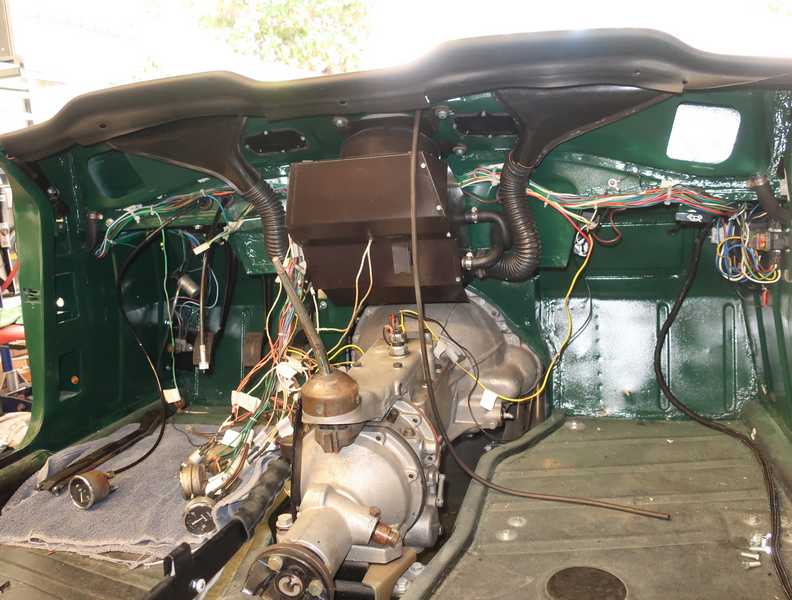
The restored heater, installed in the car. Engine-coolant lines have been connected but not the air ducts. The air outlets couldn't be installed until the dashboard cover was in place.
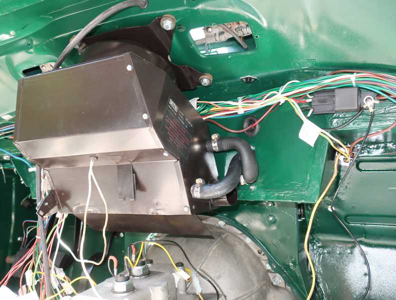
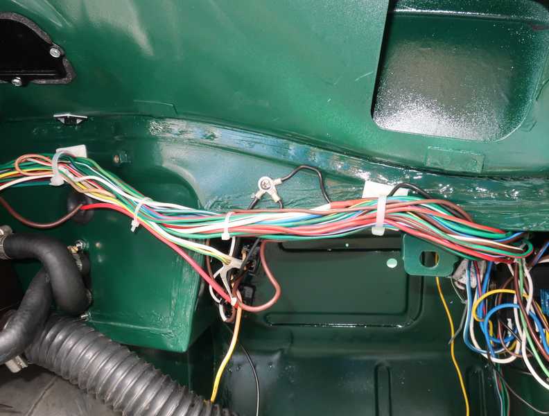
It's amusing: with all the concern for weather sealing in the TR, the covers for the wiper mechanism's access ports fit badly, originally sealed only by a large glob of seam sealer. Instead, I made gaskets from 1/8-inch closed-cell foam. I think that should make a more reliable seal.
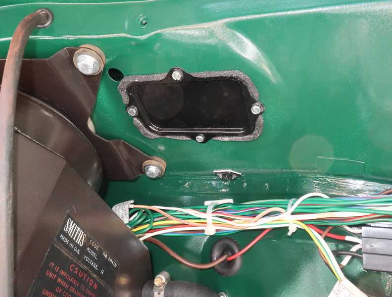
The hole to the left of the cover is for the rod that opens the fresh-air intake. It uses a special grommet that fills the opening and prevents leaks. Same idea as the one in the picture, where two wires go through the firewall.
Steering Wheel
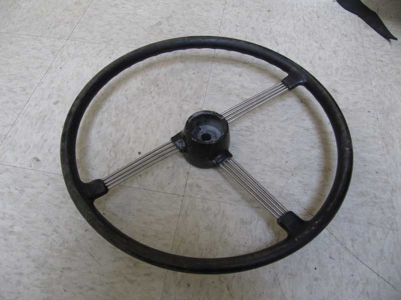
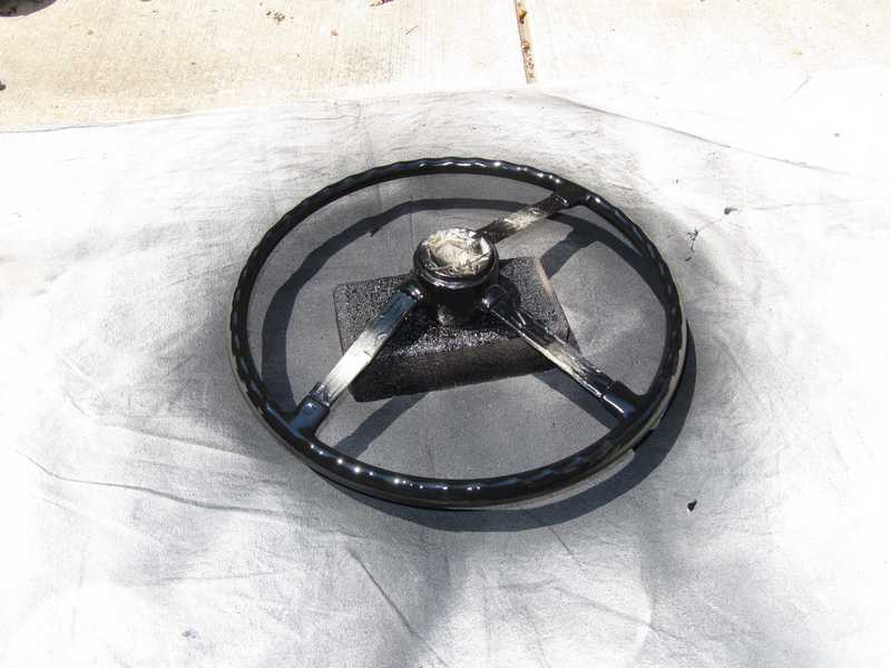
The steering wheel had a leather cover. That's usually not a good sign, as a cover often hides a cracked, disintegrating wheel surface. Not the case here; the steering wheel was indeed well worn, but it didn't show the kind of extensive deterioration that is common on older bakelite wheels.
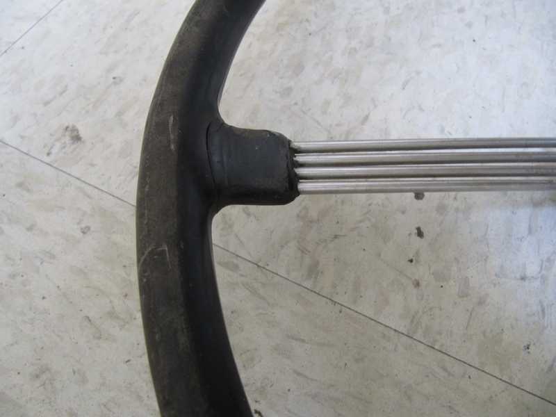
I started by removing the cover and washing the wheel. The pictures below show the wheel at that stage; the gloss on the outside surface had worn off, and there were a few small cracks at the usual locations.
Below, the steering wheel and hub have been sanded in preparation for paint. The cracks were small, so they didn't require filling.
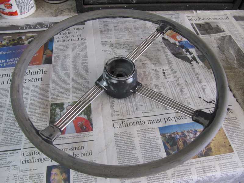
I masked the wheel, gave it a coat of primer, let it dry a few days, and finally painted it with a good-quality, gloss-black spray paint. I was satisfied with the way it turned out; I saw no need for a clear coat or any further finishing.

Seat Slides
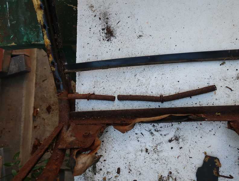
The seat slides had a fair amount of rust, but I thought they could be restored. The left and right slides are identical. They also were identically rusty.
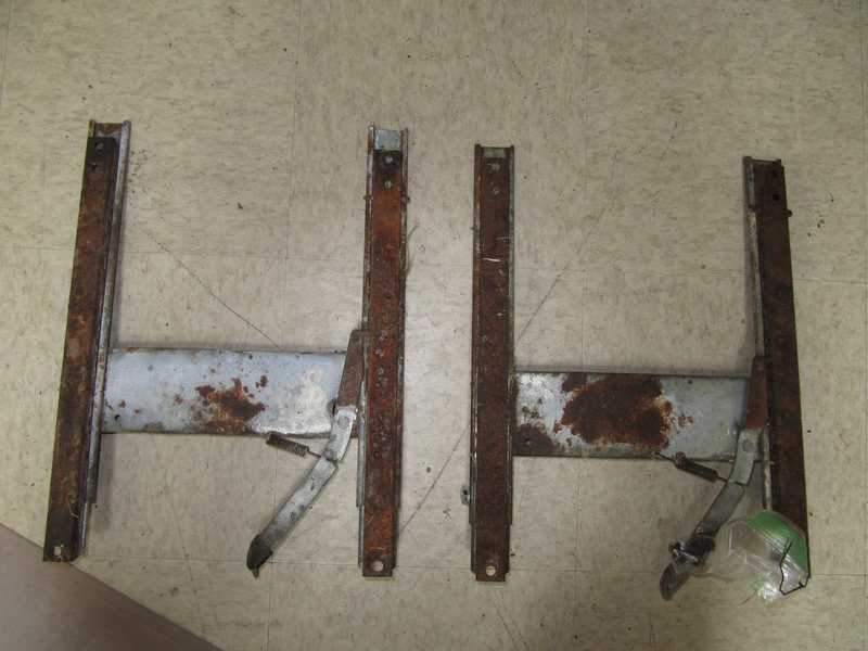
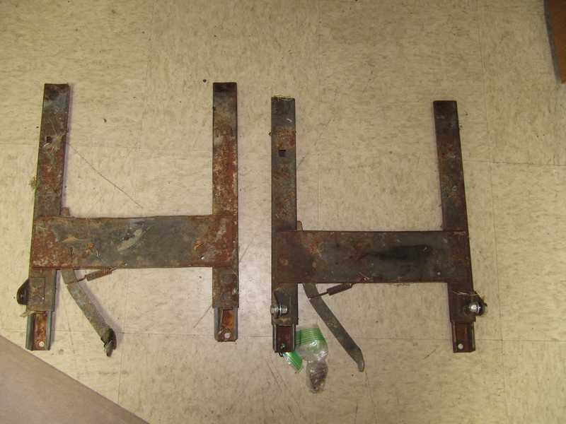
The floor-mounted rails are also identical; the locking holes on one rail are just not used. The cross piece seems to be attached with spot welds.
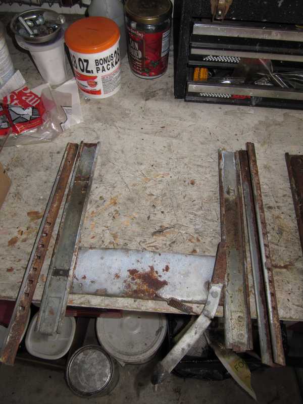
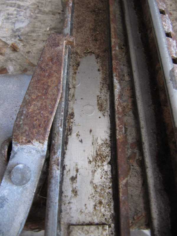
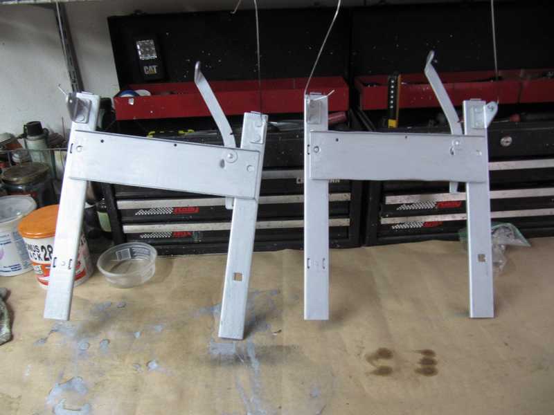
I washed the parts in detergent and wire-brushed off all the rust I could. I decided to try painting them with aluminum paint; it has worked well on some of my Porsche interior parts. It doesn't look much like a galvanized surface, but it does look vaguely metallic. That's fine for something that is not generally visible.
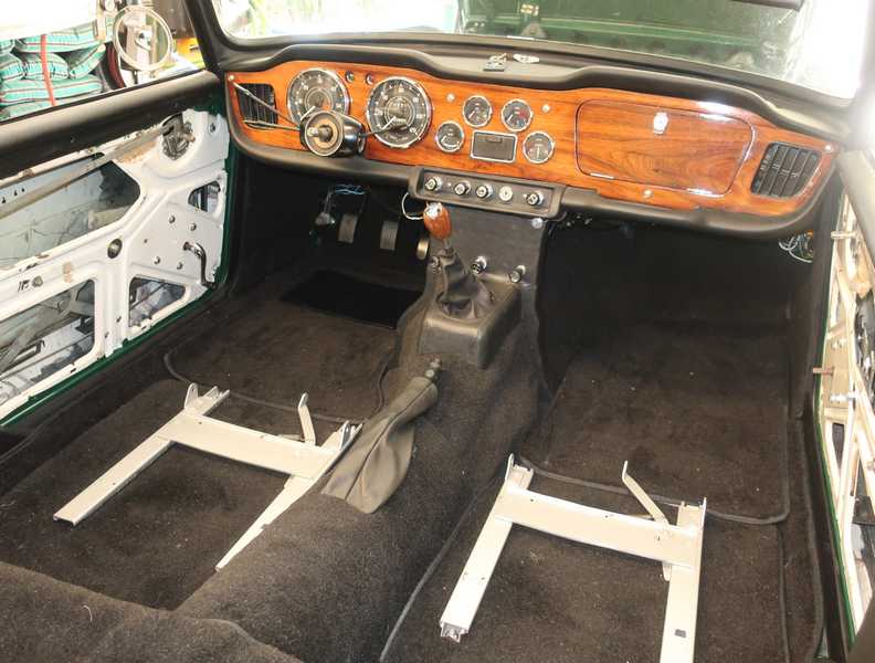
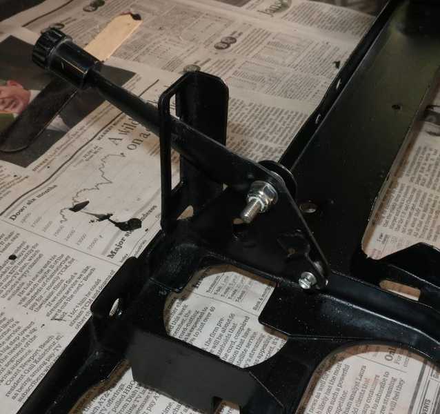
Much later, the seat slides were installed in the car. I made special mounts for them, which I think were superior the the factory installation.
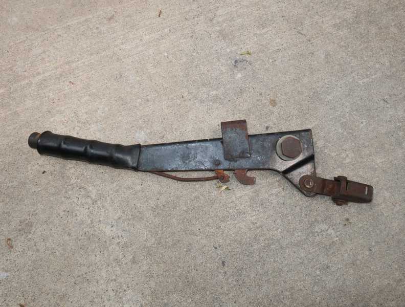
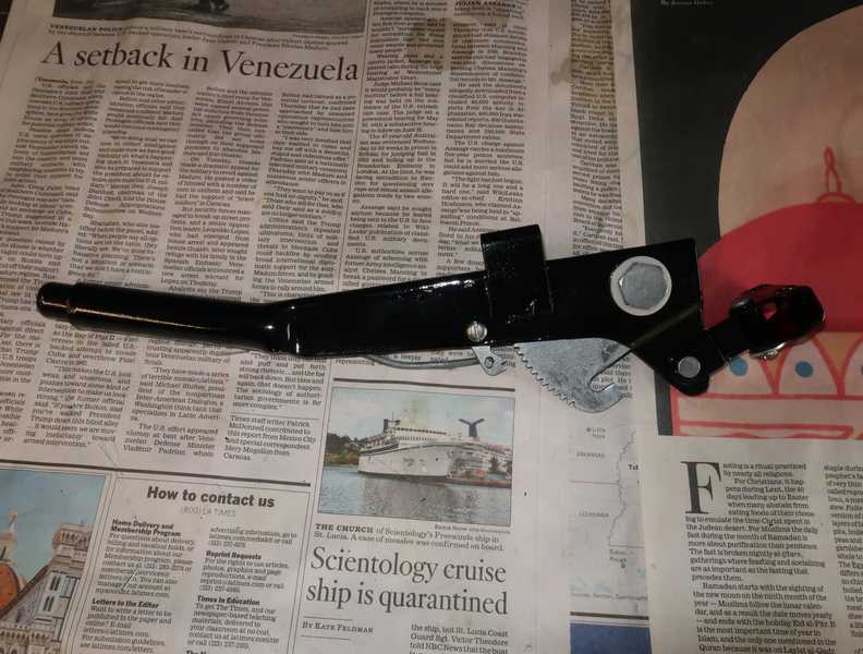
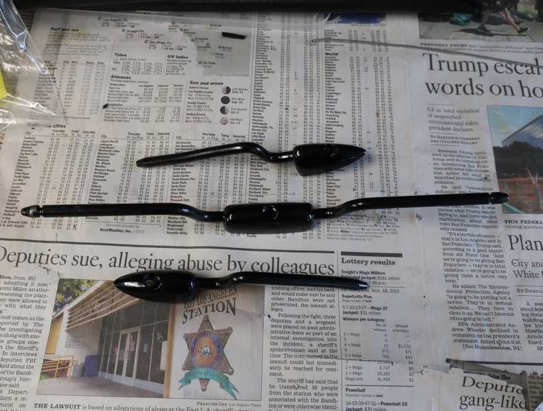
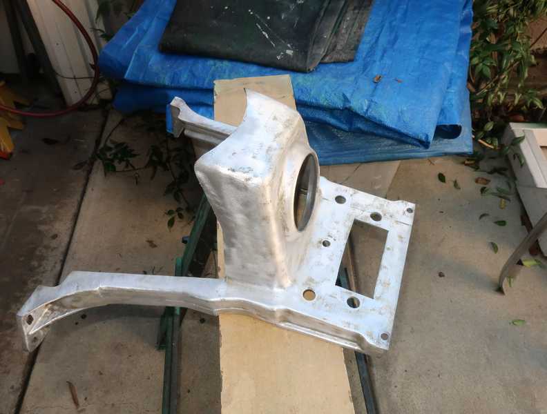
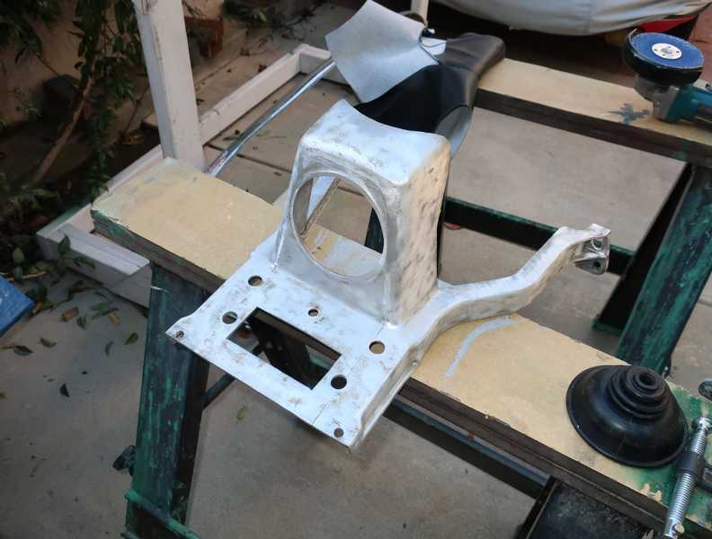
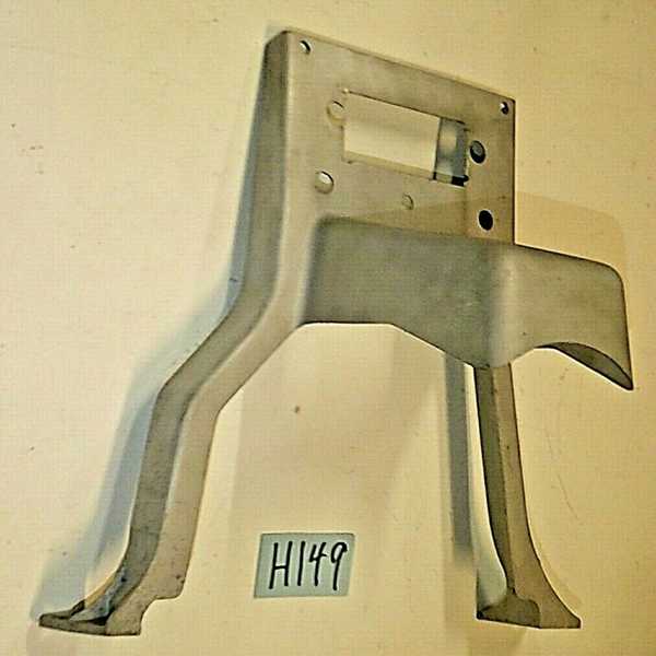
Handbrake Lever
Like almost everything else, the handbrake lever was pretty beat up.
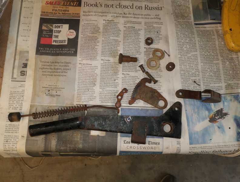
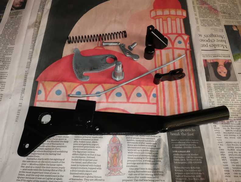
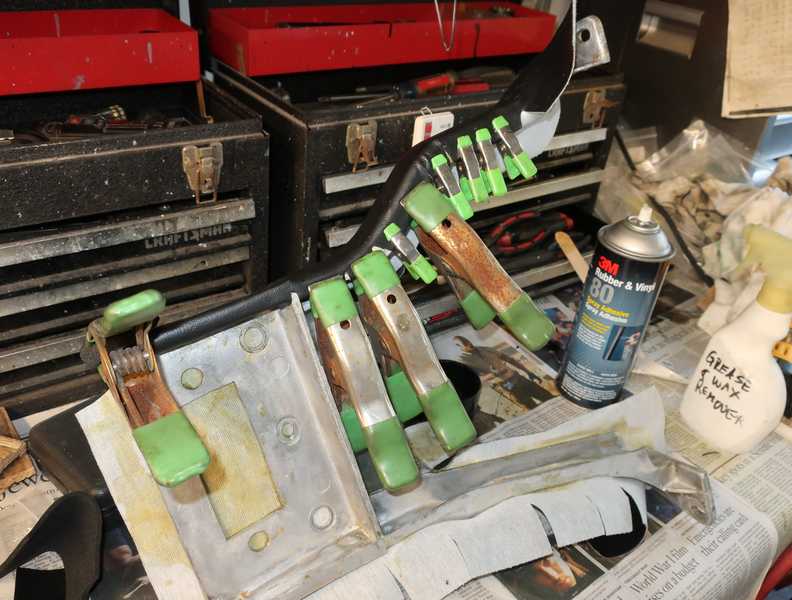
I disassembled it and cleaned, derusted, painted, and replated the parts. The button on the end had started to crumble, so I made a new one, from Delrin, on my lathe. I also made new shoulder washers, but they are not shown in the picture below.
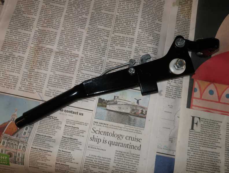
Here it is, back together. I still needed to get a new handle grip. They are readily available but had to wait until my next parts order.
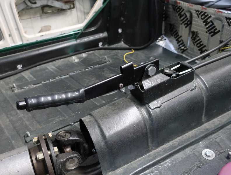
Here's the handbrake lever, installed and adjusted.
Dashboard
Inner Frame
The TR4A has an inner, steel dashboard frame as well as the decorative wood outer part. While the wood part looked good, the inner frame was dirty and, in places, rusted. The rust probably resulted from rainwater entering the air vents. It needed cleaning, rust treatment, and paint.
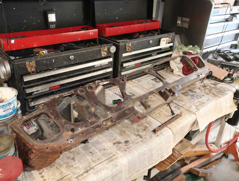
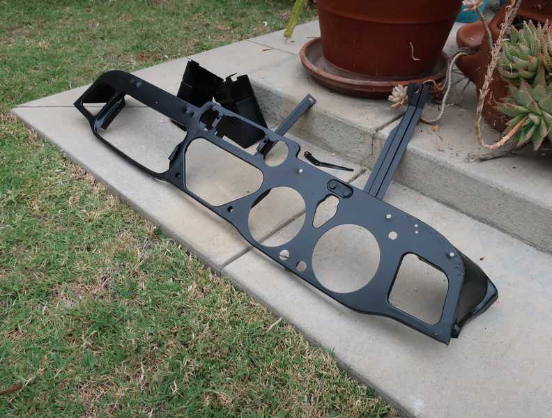
The frame was sanded, wire-brushed, primed with rust converter, and painted with semigloss rustoleum. I left the painted frame and some other dashboard parts to dry in the sun and breeze.
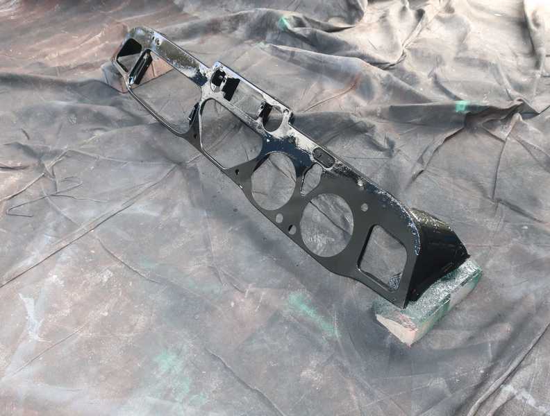
Leaving the painted parts on the patio, in the warm sun, hardened the paint quickly.
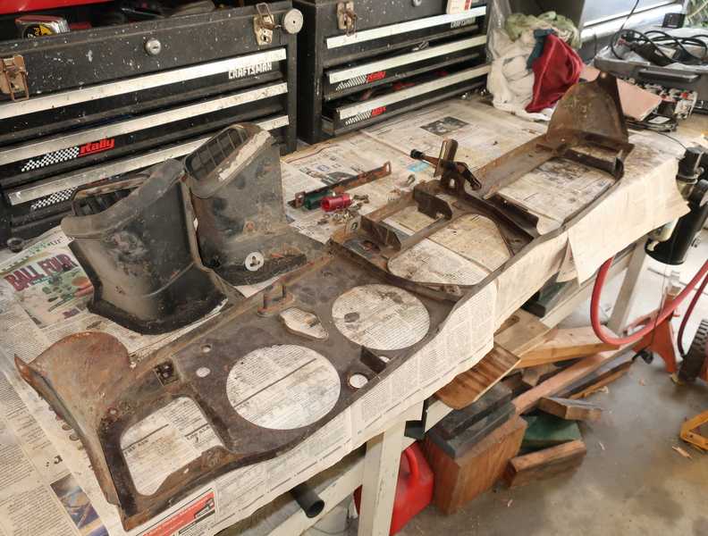
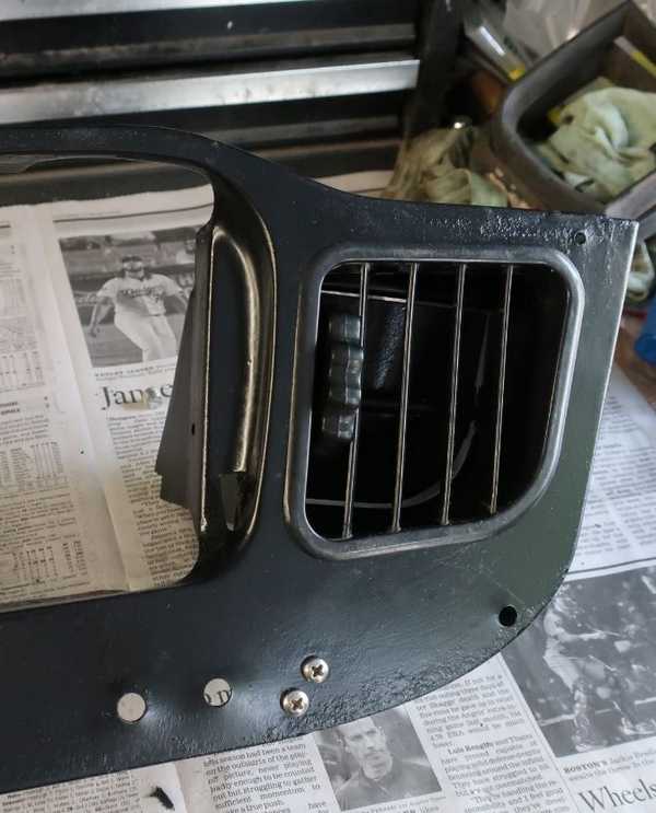
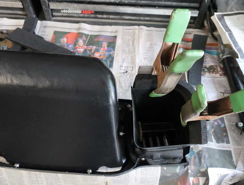
The air ducts originally used felt seals to prevent drafts. I replaced them with foam. I don't worry much about drafts in a TR4A, but the foam seal might prevent a rattle. I reused the original grille and thumbwheel.
The foam-rubber seals between the air duct and car body were not good enough to reuse. They don't seem to be available today, so I had to make my own seals. I replaced the original duct-to-body seals with half-inch foam pieces glued to the ducts. Even then, it was hard to make them seal well; I added some small pieces of 1/8-inch foam to fill the gaps.
It was easiest to install them in two pieces; below, the first piece installed on the right duct.
There's an amusing story behind the seemingly superfluous weather sealing that can be found throughout the TR4A. British cars of the era were famous for poor weather sealing, resulting in drafts and rain leakage. The TR4A designers made serious (if occasionally imperfect) attempts to address that shortcoming. I still remember a comment in a 1960s review of the TR4A, which said that it had "weather sealing good enough to keep the fussiest date happy." In a backward way, that shows what the expectations were.
Originally the vent-lid lever used a pressed-in pivot. I replaced it with a no. 12 screw and nyloc nut, and I fabricated a new cylindrical attachment for the actuating rod.
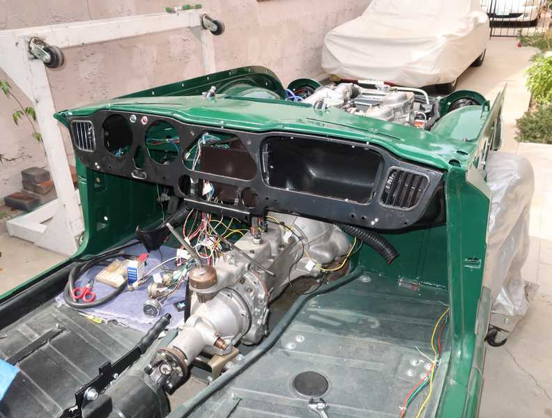
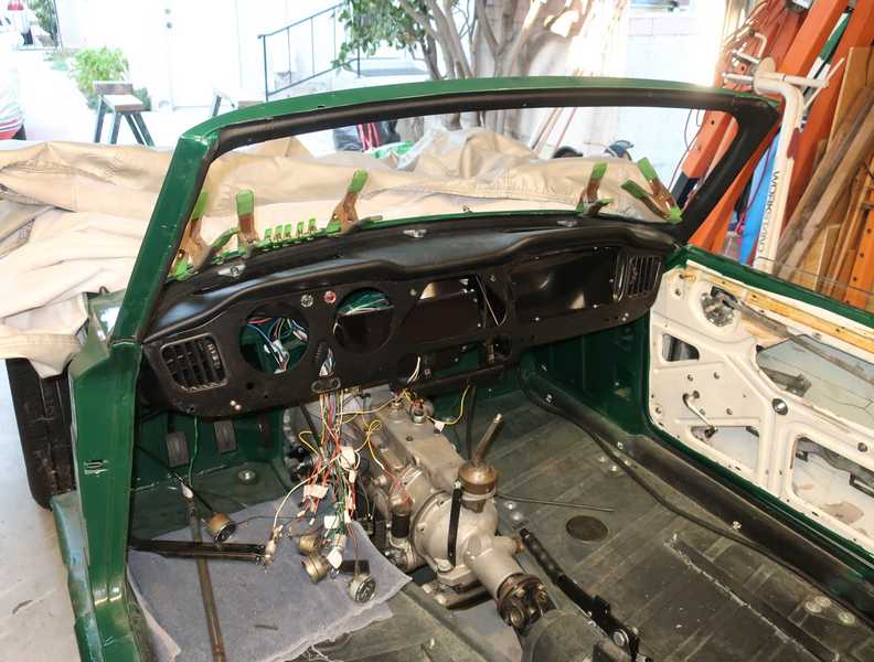
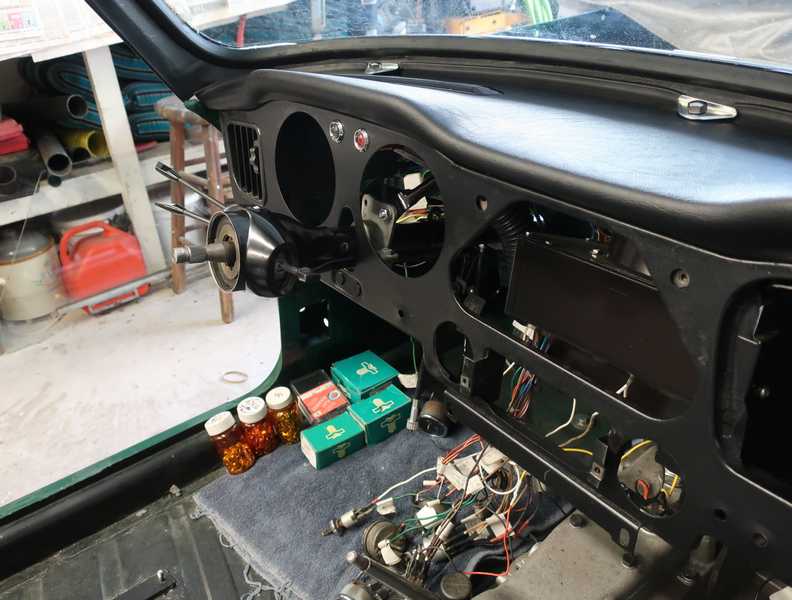
I trial-fit the dashboard to the car. I found a couple minor problems; the worst was interference between the glove box, wiring harness, and one relay. I had to nudge the harness down a little and move the relay.
The lower mount point for the dashboard, on the right, was different from the one on the left. At first, it looked like it was designed that way, but I later realized that it simply was bent. I bent it back into position, but that loosened it. I had to tack-weld it into place and spray a coat of primer for protection.

Instead of making one myself, which would have taken too much time, I used a replacement glove box. It did not fit well; I guess I should have learned by now. It took some effort and a little drilling and trimming, but I finally got it into place.
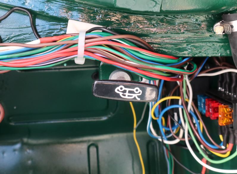
This next item is somewhere between comical and pathetic. I bought a new hood release cable, as I didn't want to take the time to restore the old one. The original cable had a round knob without an illustration; the new one had a rectangular handle with an image. It fit only one way, which left the image upside-down. The only way to fix this would be to file a new flat on the release's body or to paint over the image. I'll probably just leave it as it is, a memorial to modern replacement parts.
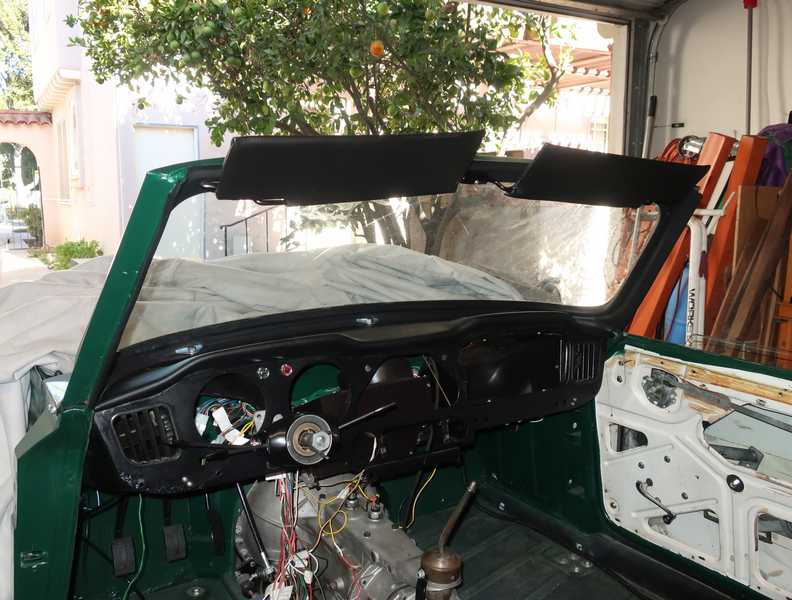
Installing the dashboard and all the stuff behind it must follow a certain order: some items must be installed before the dash, as they are not accessible with the dash in place; others can only be installed with the dash in place. First, the windshield support brackets were installed and adjusted. Next, the dash pad, defroster air outlets, and bezels were installed. Unlike most aftermarket parts, the dash pad fit fairly well. With those pieces in place, I was able to install the windshield frame. At this point, the windshield glass had not been installed; more on that here.
I had to reglue and clamp a few loose pieces of the trim that surrounded the windshield frame. I then installed the dashboard frame.
Much too late, I realized that it is best to install the lower bumper pads before installing the dash frame. Not a fatal error, but it complicated things a bit. More on the installation sequence, below.
Installing the right door permanently was necessary for aligning the windshield frame.
Wood Dash Panel
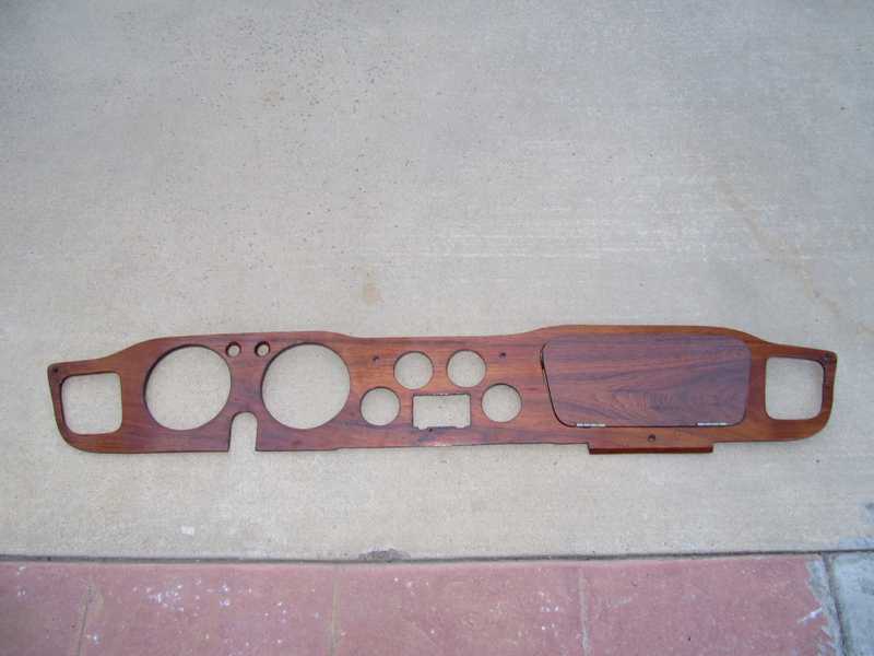
The car had a handsome, dark-wood dashboard, possibly mahogany, in good condition. Originally, the TR4A had a glossy, walnut-veneer dashboard, which I would have preferred. At this point, however, I was three years into the project and impatient to finish it, so, instead of making a new walnut dash, I restored the existing one. It was a little darker than a walnut dash, and it had an especially attractive grain pattern. In fact, I found that I liked it more than the walnut dash I made for my MG TD.
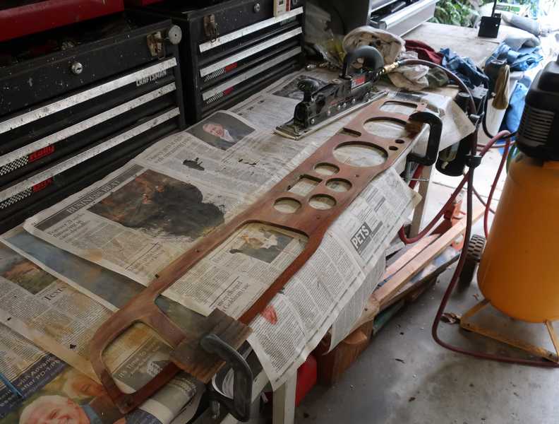
First step was sanding the surface in preparation for new varnish. I started with 120 grit to remove the old finish, then 220 and 320. I used my inline sander (actually a bodywork tool) at reduced air pressure, to slow it down, for the early sanding. The finer-grit sanding was done by hand.
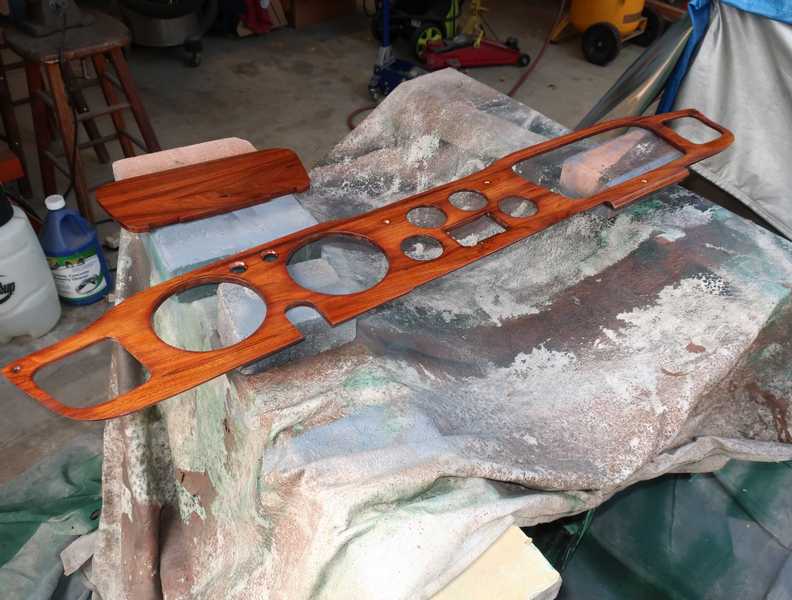
Here is the dashboard with its first coat of gloss polyurethane varnish. I applied several coats with progressively finer sanding between them. The reverse side was sanded and varnished as well, just a couple coats for protection.
Pictures later in this page show the dash panel in the completed interior.
Steering Column Installation
Once the dashboard's frame was in place, I installed the steering column. It was a straightforward operation.
Restoration of the steering column is described here.
Because I used Molex connectors for all the electrics, it was a simple matter to connect the column's wiring. I left the tags in place until I was sure that everything was working.
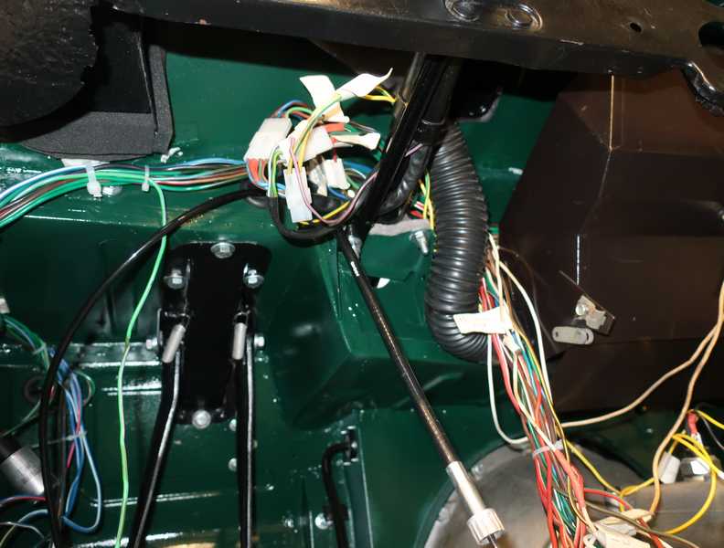
Below, the steering column and shaft in the engine compartment. There should be a seal in the firewall, but it wasn't included in my seal kit, and it wasn't clear to me that a rubber grommet would seal properly in the angled firewall, anyway. I later made a seal out of half-inch closed-cell nitrile foam; it looked OK and certainly sealed more effectively than a rubber grommet would.
Cables
The TR4A has four control cables: the choke cable, two heater cables, and the hood release. For some unfathomable reason, replacement heater and choke cables are stupid-expensive, so it is worth some effort to restore the existing ones. I bought a new hood-release cable, and regretted it.
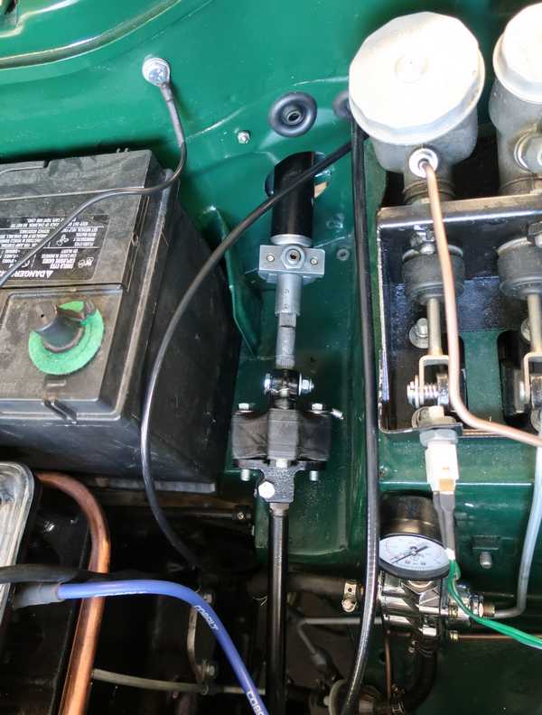
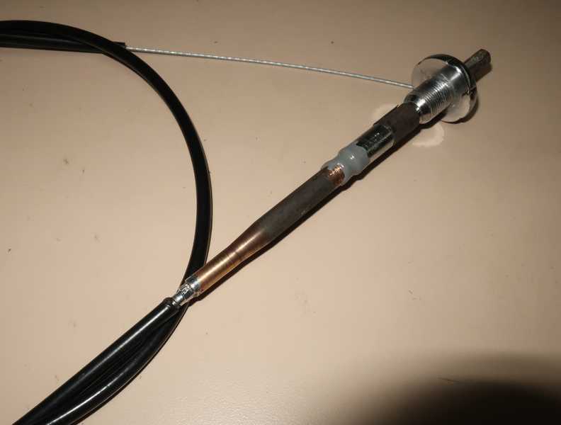
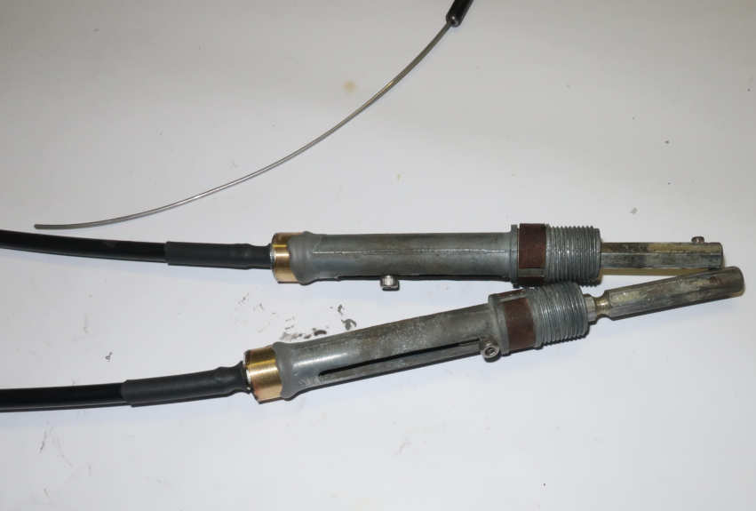
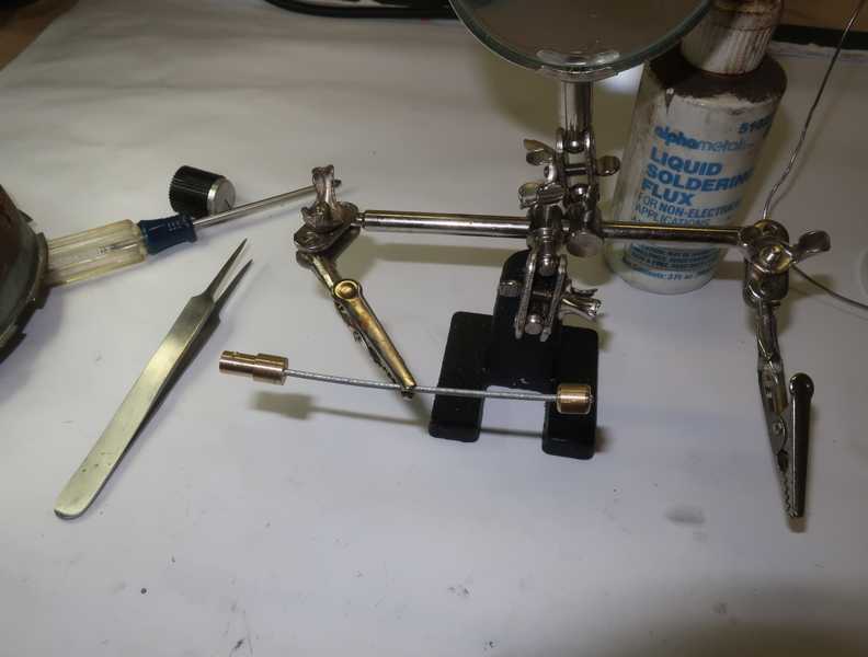
The picture below shows a restored choke cable. I replaced the rusted outer sheath with a bicycle brake-cable sheath; for the cable I used a bicycle derailleur cable, as it was the same diameter as the original choke cable. I soldered the sheath into the tapered brass section of the control. The brass taper was loose at the body of the control; I would have preferred to solder it, but solder would not adhere to the chromed body. Instead, I used JB Weld to hold it in place. I soft-soldered the cable into place after drilling out the old one.
That brown band that encircles the body of the control is a spring. Under it is a small, D-shaped piece of metal. They comprise a simple, spring-loaded mechanism for locking the choke in position. The metal piece was long gone; I had to make a new one from 0.031-inch shim stock. The body of the cable assembly used an metric nut that required an 18 mm socket; clearly, this was not an original cable.
Below are the heater cables, minus their mounting hardware. The controls are identical, but the cable lengths are different. The internal cable is solid, as it must push and pull identically. I used bicycle brake-cable sheath for the outer part and 0.045" tempered stainless-steel wire for the inner. The brass end-adapters were made on my lathe; they are soldered to the cable sheaths and attached to the control bodies by JB Weld epoxy. I replaced the balls under the springs, which provide detents; they are ordinary 3/16" ball bearings.
Instruments
The instruments seemed to be in good condition, most needing only cleaning and polishing. The chrome bezels at first looked pretty bad, but, in fact, they were covered by a common type of crud buildup, which came off easily. Then, the underlying chrome, which was actually in good shape, was buffed and polished.
Fuel Gauge
The fuel gauge is shown below. I took it apart, cleaned the interior and face, and touched up a couple spots where paint had come off. Its bezel had the usual layer of crud, which was easy to clean off, and a little buffing and metal polish restored the chrome nicely. This procedure was used with the other instruments.
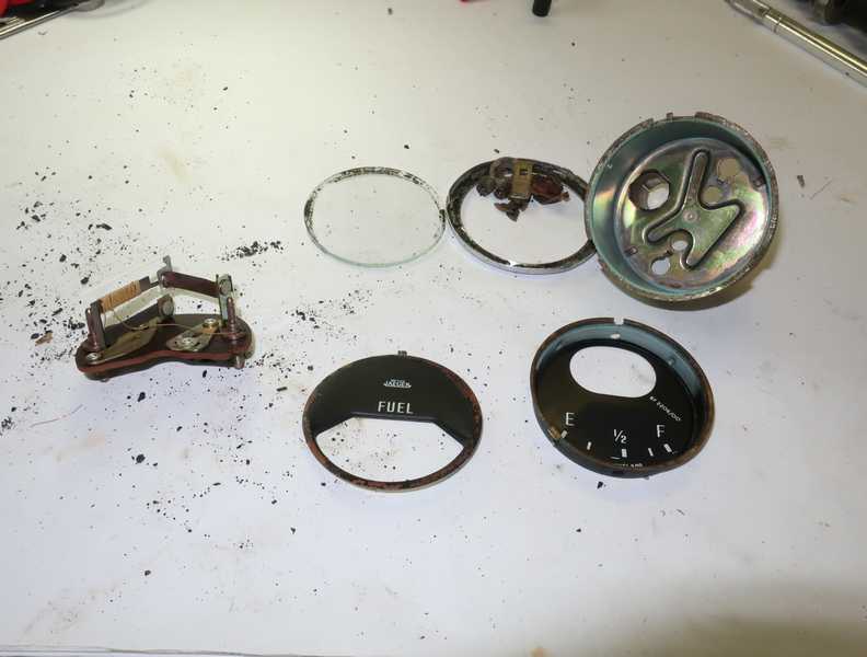
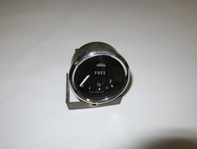
It's interesting that the fuel gauge is not a conventional, moving coil meter. It uses a bimetallic thermal strip with resistive wire wound around it. That gives it a slow response, exactly what you want in a fuel gauge. I tested the gauge on the bench; full scale required 100 mA.
Temperature Gauge
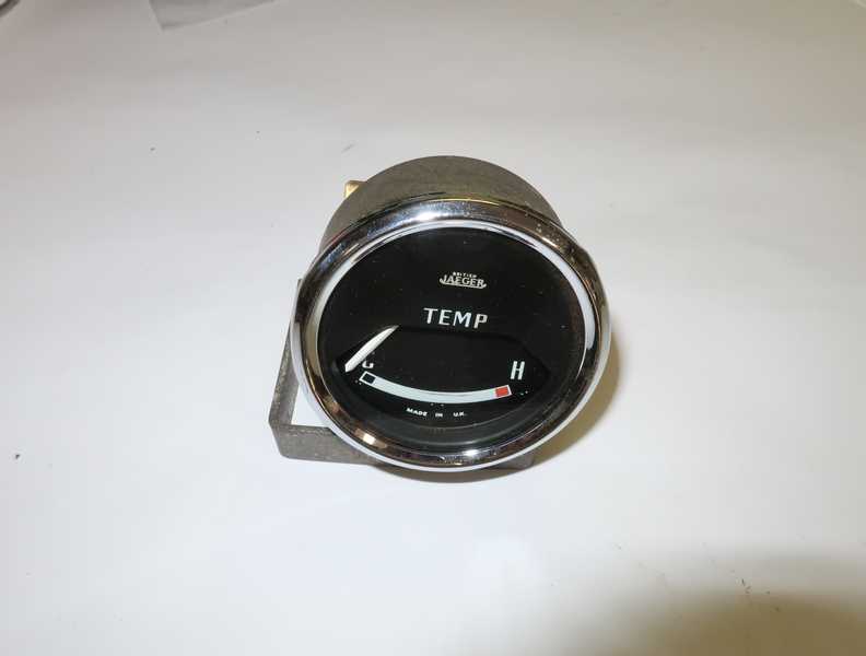
Earlier British cars used a thermal-mechanical temperature gauge. The TR4A, I am pleased to report, uses an electrical one. It is shown below, as it came off the car.
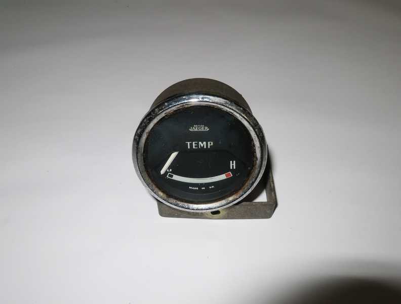
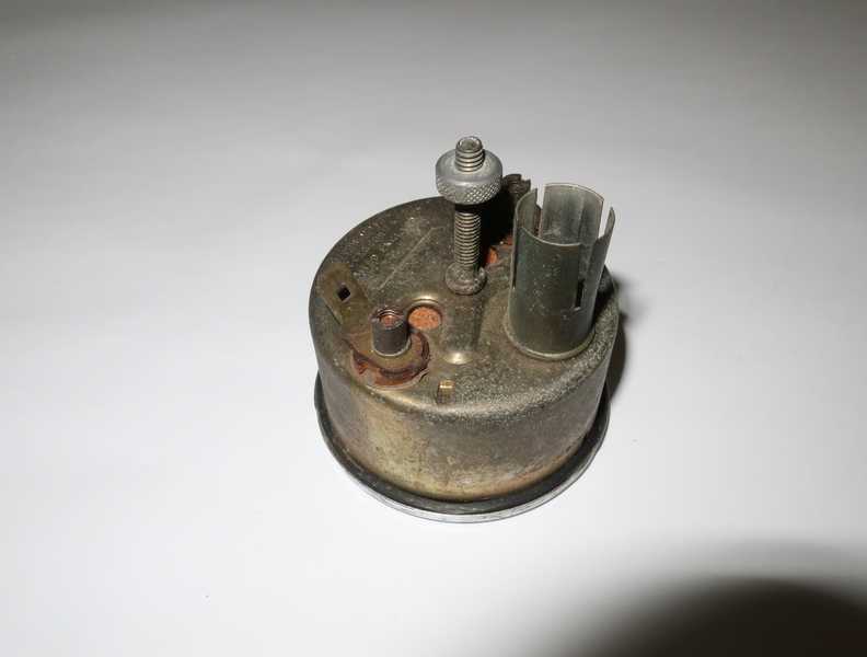
The temperature gauge, like the fuel gauge, uses a heated bimetallic strip, and actually appears to be identical internally. It required only the same work as the fuel gauge. Below, the restored gauge.
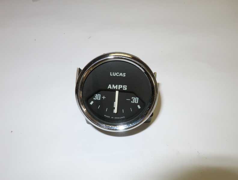
Ammeter
The ammeter carries the entire current of the electrical system. (Anyone thinking single-point failure? I am. But that's just the way it is.) Below, the ammeter as it came off the car. The large tabs are for the high-current connections.
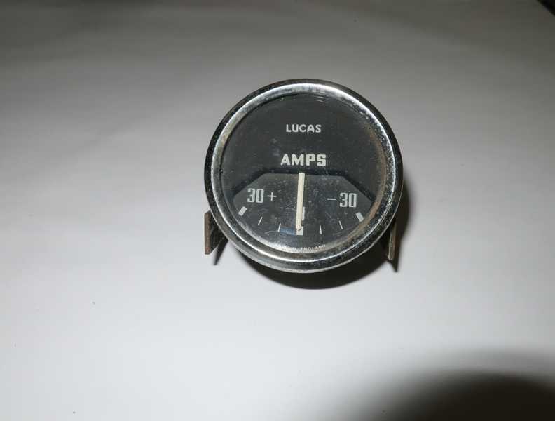
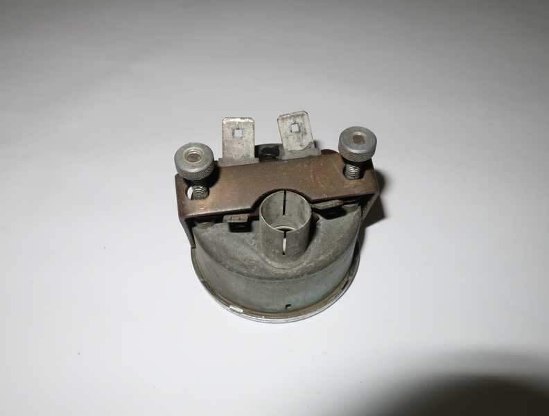
The ammeter required only disassembly and cleaning. It is shown below, finished.
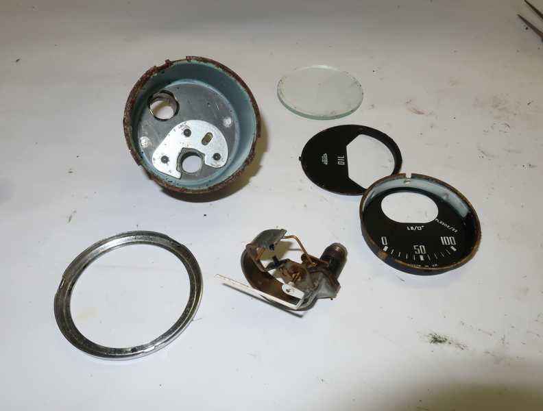
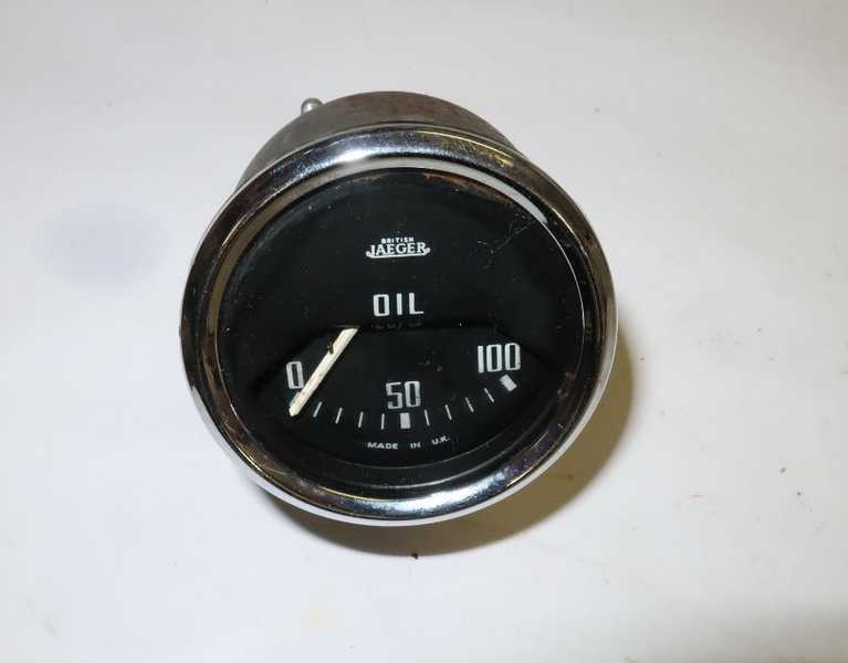
Oil Pressure Gauge
I had checked the oil pressure gauge against a known-good pressure gauge and determined that it was accurate. So, no calibration needed; just cleaning.
Tachometer
The mechanical tachometer is typical of virtually all British cars of the TR4A's era; higher-end cars, like my 1967 Porsche 912, had electronic ones. I have converted a number of mechanical tachometers to electronic operation.
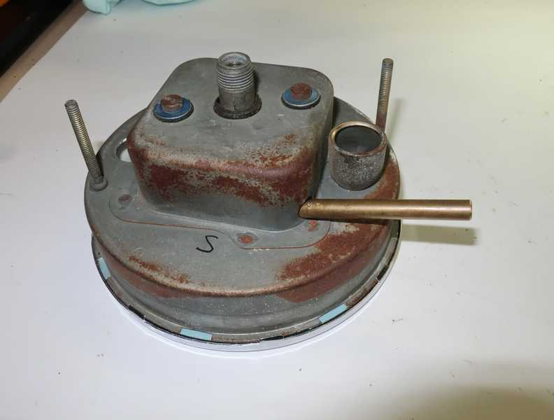
On initial inspection, the parts seemed to move smoothly; a good sign.
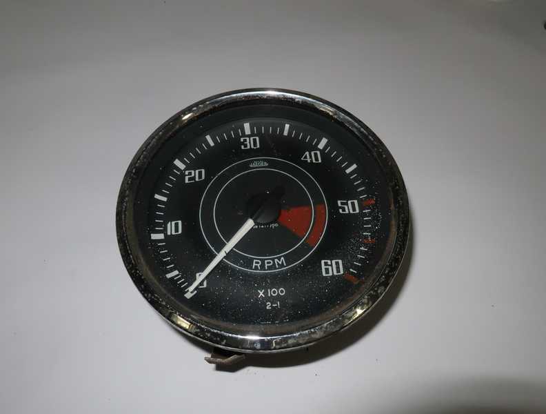
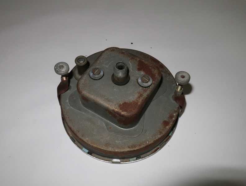
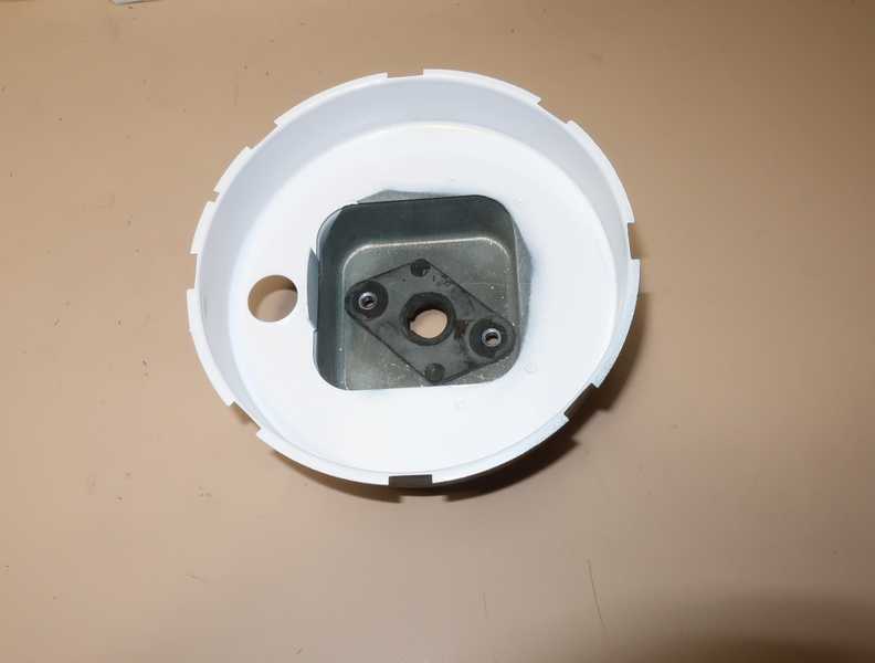
The tach needle sometimes didn't come to rest at zero, so I took it apart to give it a more serious cleaning. The paint on the inside of the case had started to flake off, getting into the mechanism. First step was to sand off the old paint and repaint it. (The white interior is necessary; it acts as a diffuser for the gauge illumination.) I disassembled the innards only enough to clean and relubricate them; nothing more was necessary.
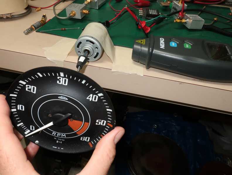
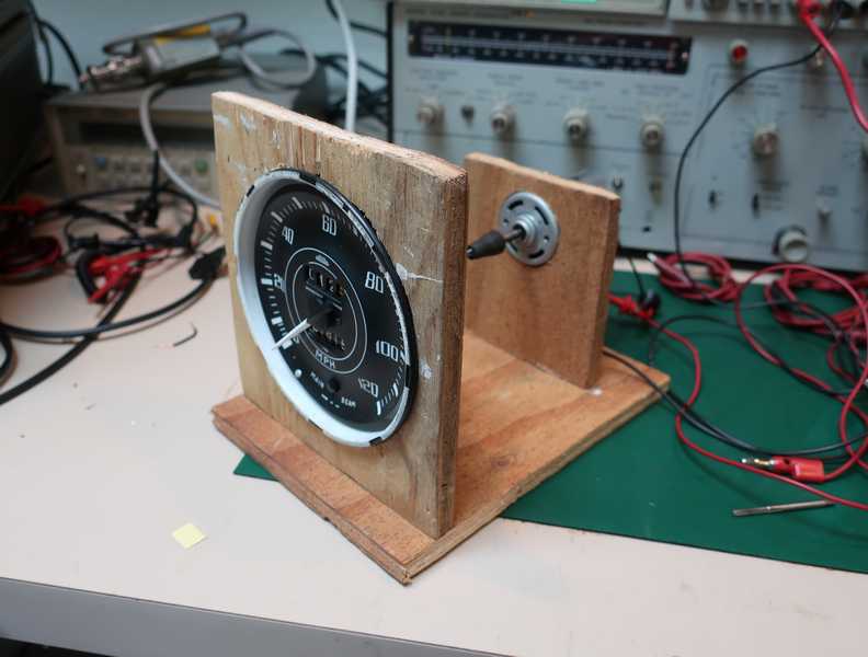
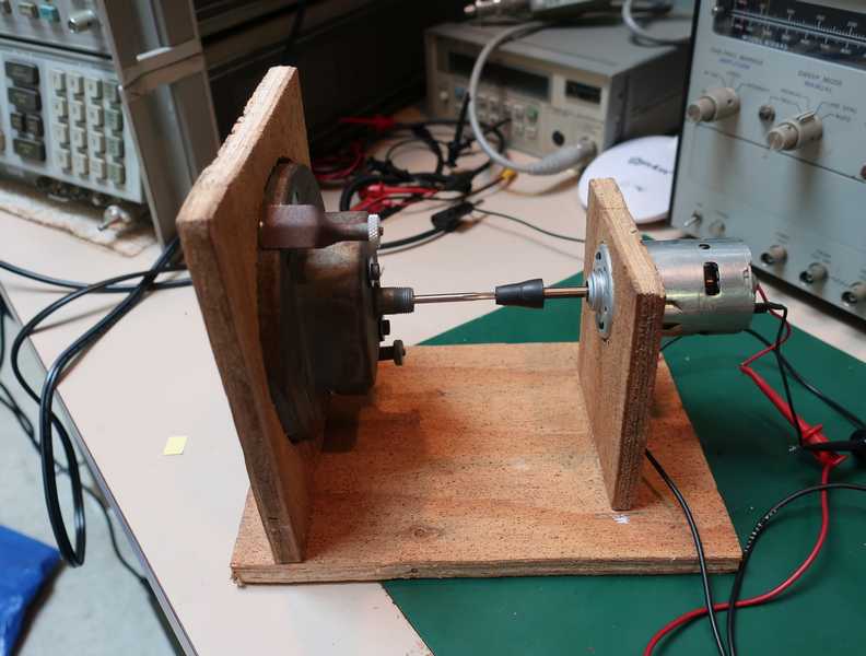
Here's my super-high-tech calibration bench. I use a small electric motor, run off a variable-voltage power supply, to turn the tachometer. An optical tachometer gives me the motor speed. Note the "2-1" marking at the bottom of the tach face; it means that the indicated speed should be precisely twice the input-shaft speed.
Usually the tachometer can be calibrated reasonably well just by moving the pointer's initial position. If that's not good enough, changes to the magnet or cup must be made, and that's much more difficult to do well.
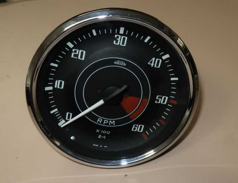
Below, the finished tachometer.
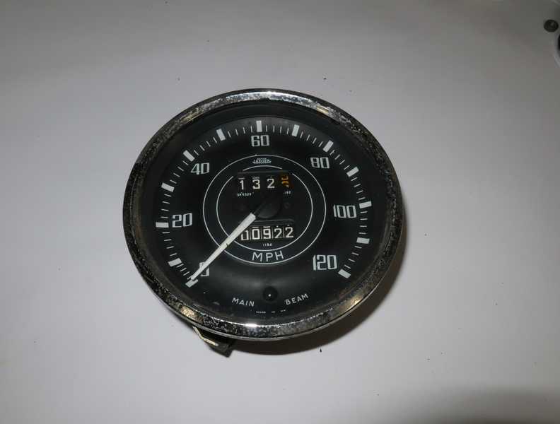
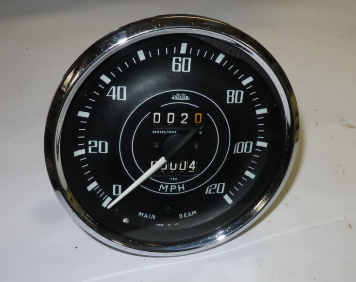
Speedometer
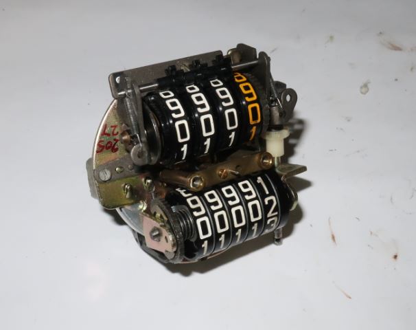
The operation of the speedometer is similar to that of the tachometer, with the addition, of course, of the odometer mechanism. The speedometer's parts, however, did not move smoothly; the input shaft seemed to drag, and the pointer was sluggish and did not return fully to zero. It needed attention.
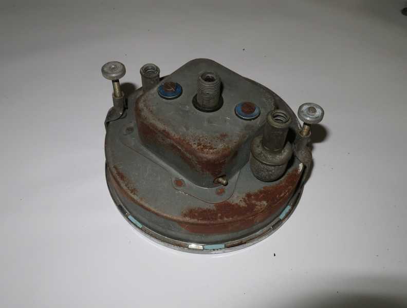
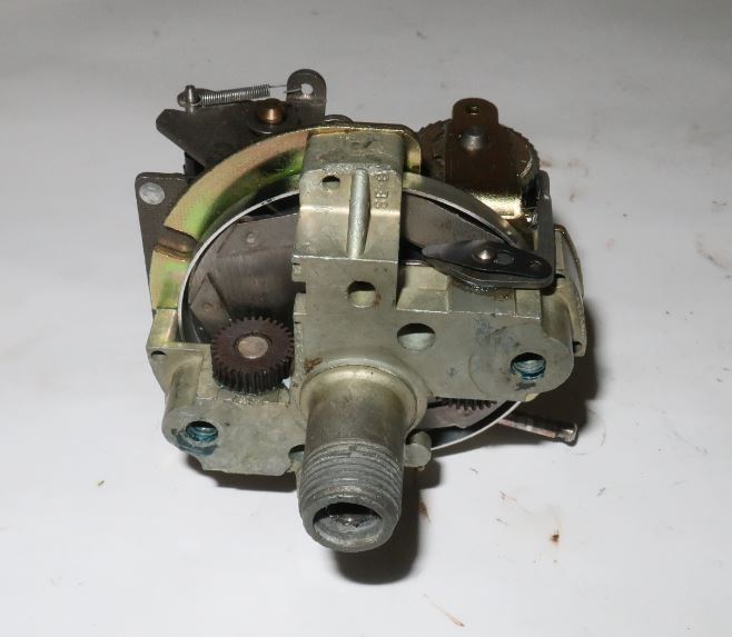
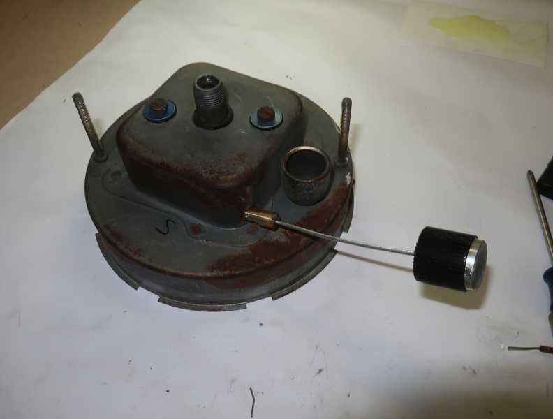
The major parts of the speedometer are easy to disassemble. Below is the magnet and frame; removing the two visible screws allows the magnet to be removed, so the input shaft can be cleaned and relubricated. As I suspected, the grease on that shaft had become stiff and dirty. Removing the magnet also allows the worm-gear assemblies, which drive the odometers, to be disassembled and relubricated.
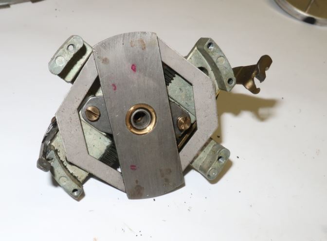
I also put a drop of graphite lube into that hole in the center, which supports the cup's shaft.
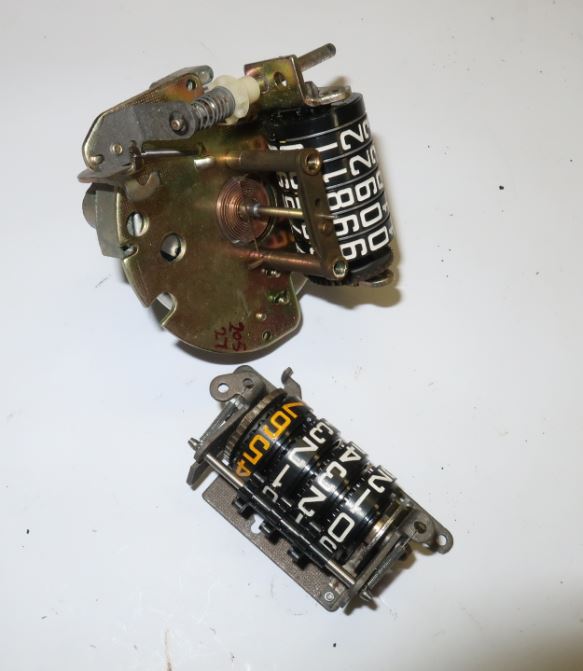
The odometer assemblies are easy to remove and to disassemble, but they're a genuine bitch to put back together. The shaft with the spring supports the cup; the adjustment at the upper end sets the allowable play, which should be just adequate to allow free movement. The problem with the pointer was fixed by resetting this adjustment.
I zeroed the main odometer so it indicated mileage from the restoration. That's the only "mileage" that has any meaning in a car this old.
The shaft that is used to zero the trip odometer was missing. I made a replacement from a 1/4-inch brass rod. It is attached to the adjuster stub by a steel pin.
Like the tachometer, the speedometer has a calibration number printed on its face: 1184, just under the odometer. That's the input-shaft speed in RPM for a 60 MPH indication. I checked the speedometer's calibration with the same test system I used for the tachometer. The speedometer now looks good and should be reasonably accurate.
Later Work
I had some problems with the speedometer's needle sticking at a couple points in the scale, and I never liked that brass rod used to zero the trip odometer. I removed the speedometer to deal with these details.
I tweaked the screw adjustment that takes up looseness in the pointer mechanism; I had it too tight, and that seems to have caused the sticking. A second problem was wear between the odometer worm gear and its mounting plate; that made the magnet loose and sloppy. A third was some interference between the watch spring and pointer shaft. The spring must not rub on anything, including itself, as the pointer moves; if it does, the pointer can bind. I fixed all these problems.
I made a new adjuster from some machined parts, a piece of bicycle brake cable, and a radio knob. The two brass pieces are soldered to the cable, and the radio knob is simply epoxied. This didn't work perfectly, as the cable often would wrap up when I tried to zero the trip odometer. I later put a piece of brake cable sheath over it, and that cured the problem.
I made a fixture for holding the speedometer while checking the calibration. It's just a simple plywood fixture, made from some scrap plywood, but it makes the job much easier and more precise.
I rechecked the calibration; it was right on. I reinstalled the speedometer and took the car for a test drive. The speedometer worked as it should, and it is now much easier to zero the trip odometer.
Assembling the Dashboard
Gauge Installation
Installation of the gauges was largely straightforward. I chose to install them after the dash was in place. Sometimes they are installed in the dash panel before it is installed on the dash frame, but it can then be tricky to connect the wiring and oil-pressure line.
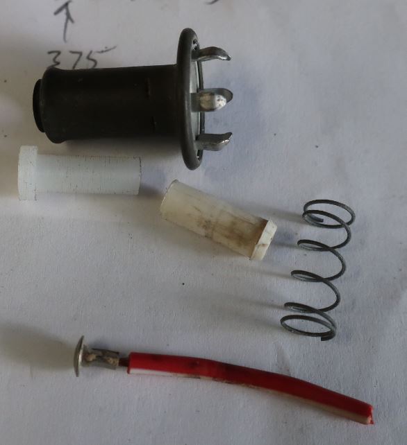
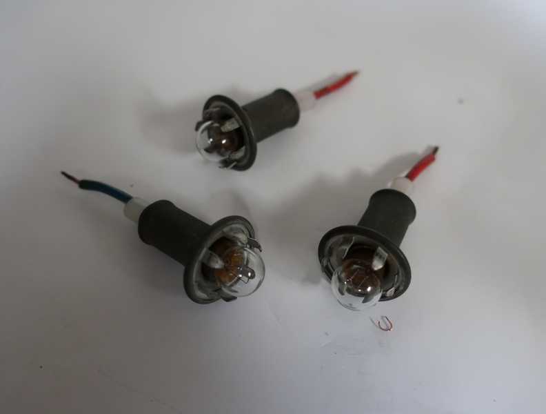
As I restored the wiring harness, I was puzzled by the fittings for the three lamps that were mounted in the speedometer and tachometer. When I tried to connect them, I realized that they were actually the remains of the broken internals of the three lamps. I made new parts out of nylon and was able to restore all three lamps. The new nylon piece and the old (white) plastic part are shown in the left picture, below.
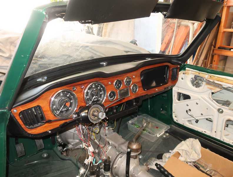
Below, the dash, with all the instruments installed.
Lower Pads and Switch Panel
I connected the wiring to the gauges before installing them into the dashboard. There is little room behind the dash, and it seemed easiest to attach the wires, insert the gauges into their holes, then install the clamps. The alternative was to install the gauges first, then to connect the wiring after the wood panel was installed.
To install the pads, I had to loosen the outer wood dash panel and remove the screws from the lower right and left corners of the dash frame. By then, the instruments were mounted, and I also had to loosen some of them. It was tricky to get everything loosened enough to get the pads into place. The outer pads are attached to the dash frame by 10-32 machine screws; the center panel by no. 8 metal screws.
Installing the switches into the panel was not difficult; I had already wired them for electrical tests. Installing the choke cable into the panel was a supreme bitch, because the nut was almost inaccessible once the panel was in place. I don't know how a hapless owner would replace a choke cable after the car was all together; I hope I'll never have to.
I bought a set of glove-box door hardware from Rimmer. It was a disappointment. Parts that should have been chromed were just stainless steel, not finished off well, and the screws were the wrong size. Still, the parts were better than my old ones, so I used them.
The door didn't have a hole for the latch. I had to drill one, yet another heart-in-the-throat operation. I think it came out OK; it latches well, sits flush, and the wood grain of the door matches the rest of the panel nicely. At this point, the dashboard was complete.
Some Hindsight Regarding the Installation Sequence
I determined the best installation sequence by trial and error, mostly error. The dash assembly and installation could have been easier if I had realized that the sequence of operations mattered so much. Here's how I wish I had done it:
- Install the wiring harness, heater and its plumbing, wiper mechanism, access covers for the wiper mechanism, and any other bits that have to go behind the dash.
- Install the padded dash top.
- Install the air outlets, bezels, and air hoses for the defroster.
- Install the windshield frame and at least one completed door. Align the frame and tighten it well; some of those bolts never will be seen again. Also install the three hold-down clamps along the top of the dashboard pad; it's much easier before the glass is installed.
- Install the windshield glass.
- Check the fit of the dash frame and remove it from the car.
- Install the lower pads onto the dash frame.
- Install the choke cable into the switch panel and install the switch panel onto the dash frame.
- Install the dash frame.
- Install the steering column and connect its wiring.
- Install the wood dash panel.
- Install the gauges. Start with the fuel gauge. Pull the wiring out through the dash, connect it, and insert the gauge into its hole. Then, reach up behind the gauge and attach the clamp and the ground wire, which is daisy-chained from gauge to gauge.
- Install the oil pressure gauge in the same manner.
- Install the ammeter, ashtray, and temperature gauges in the same manner and in that order.
- Insert the ignition and turn-signal lamps into their plastic lenses.
- Insert the speedometer into its hole after connecting the cable and lamps. Connect its clamps and ground wire.
- Install the tachometer in the same matter as the speedometer.
- Install the controls into the switch panel. They should be connected before installation.
- Run the choke cable through its grommet in the firewall and connect it to the carburetors.
I understand that some restorers install the gauges into the wood dash panel, connect them with the panel held close to the dash frame, and finally install the panel. I'm sure that works, but I doubt that it would be any easier than the process I've described.
The shifter console (not shown here) was less difficult, as there were only three items mounted on it, and they were much more accessible. Of course, it must be installed after the dashboard and the transmission cover.
Sun Visors
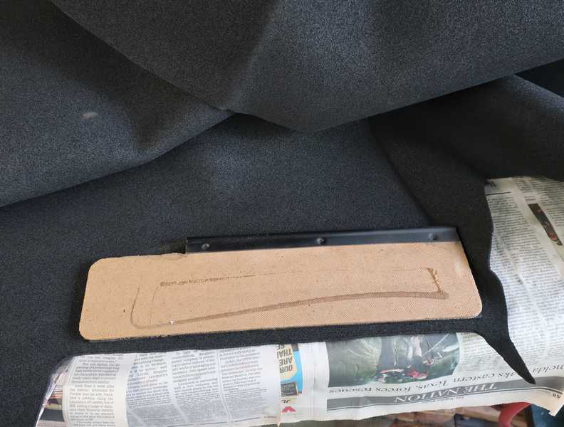
The sun visors originally had a vinyl exterior. Internally, each had a fiberboard panel, a metal hinge, and some foam padding. Only the panels and hinges were worth keeping; the covers were faded and brittle from a half century of sun damage. Below, a visor, disassembled.
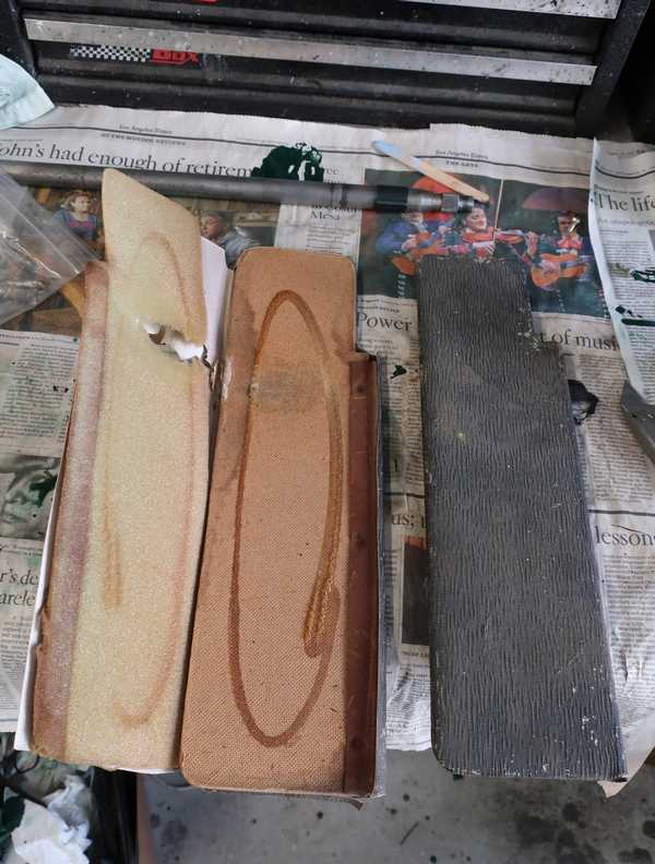
I repainted the hinge, then cut 1/8-inch foam to cover the panel and glued it into place. The foam filled up space in the visor and gave it a softer, more uniform feel and appearance.
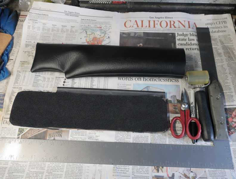
I sewed new covers from automotive vinyl and inserted the panels into them. The vinyl is tough; an ordinary sewing machine was adequate for stitching the two layers, but that was its limit. To close the ends, I turned the ends inside and whip-stitched them by hand using heavy thread and leather needles.
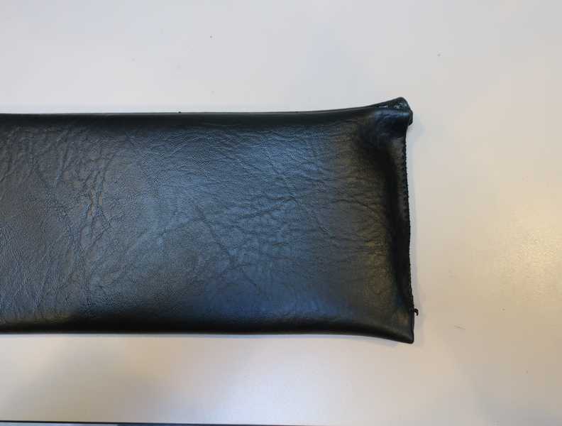
I repainted the supports and mounted the visors on the car. They don't look exactly like the originals, but I think they are fine, and the marine-grade vinyl I used should have good sunlight resistance.
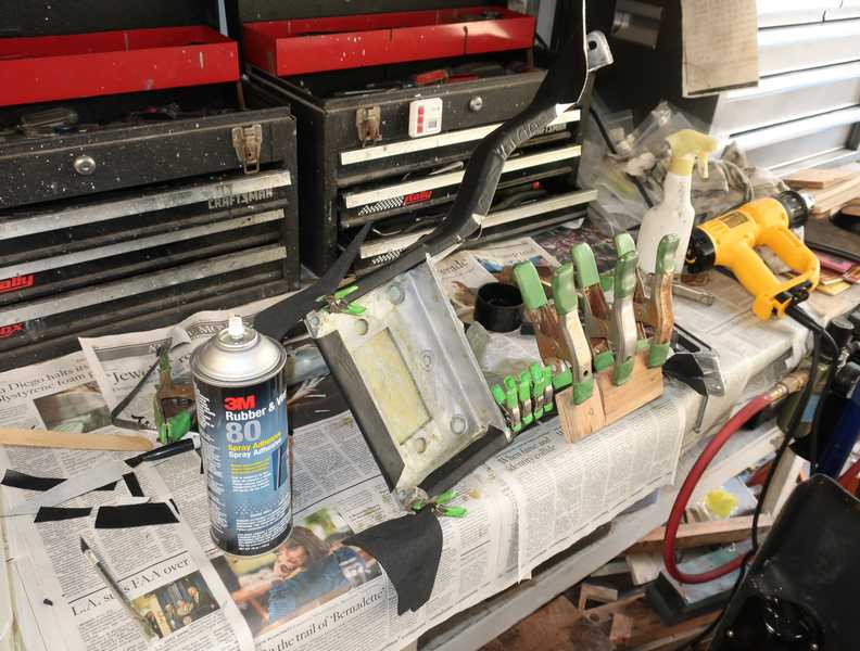
Shifter Console
Or dash support, or center console, or whatever people are calling it these days. I think it must have a dozen names. The original was a little beat up and, like the rest of the dash trim, it just looked worn out.
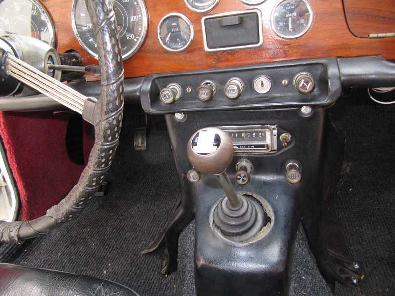
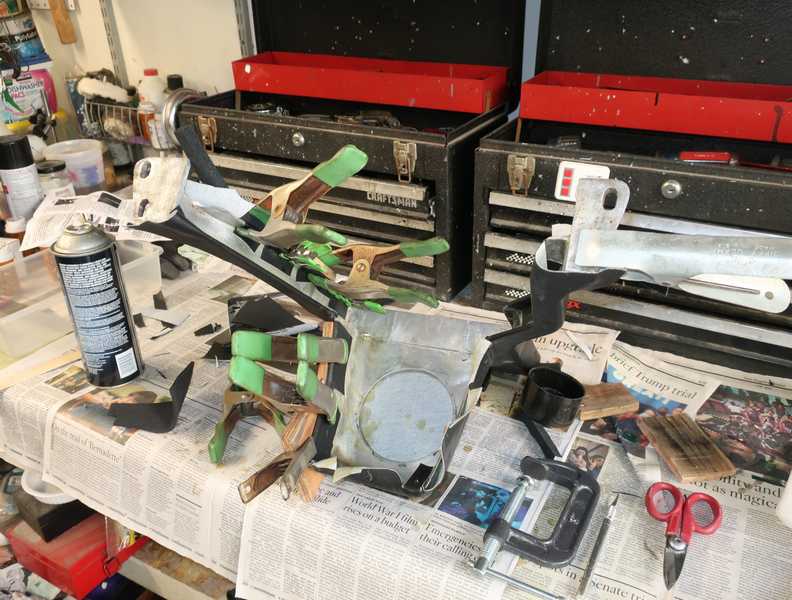
My console is an early one, with a raised rim around the shifter opening (left, below). It is sometimes called the "volcano" console. New covers for that console don't exist, so I had to adapt a later one. First priority, after removing the old cover, was grinding off that rim, so a later cover had a prayer of fitting (right). I used an angle grinder with a coarse sanding disk. Also, all the foam remaining from the old cover had to be cleaned off.
Below is a picture of a late console. You can see that it is simpler and smoother, thus easier to recover. Mine, in contrast, was a bitch.
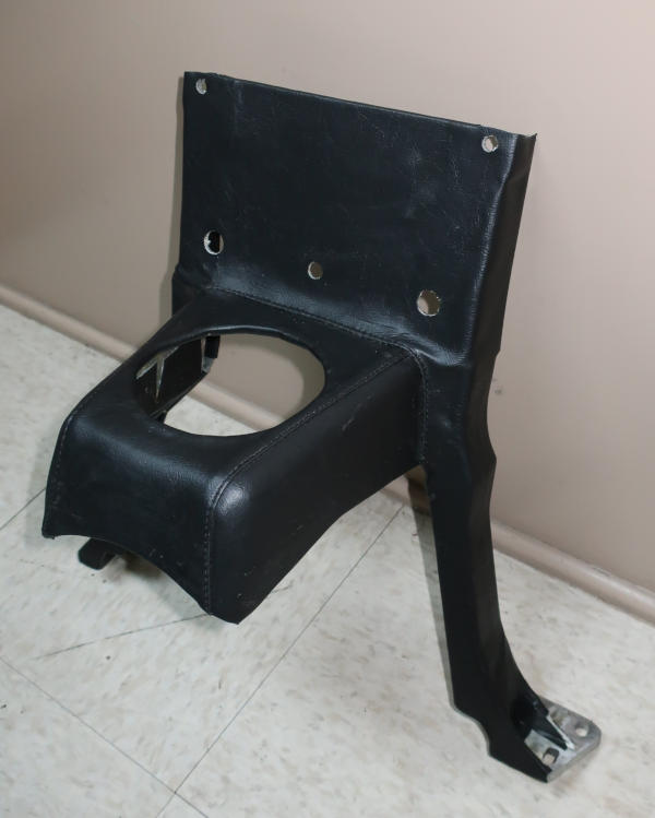
Two kinds of covers are available: a molded one, which costs a bit over $200, and a sewn one, which is $50. (Some of the usual suppliers charge $100 for this item, which is nothing more than a vinyl cutout with a couple sewn seams!) Being a cheapskate, I decided on the latter, even though it's more than a little overpriced. It was quite a bit more work to install it, and it doesn't look exactly like the original, but I think it's acceptable.
Installing the cover is a tedious process of fitting, stretching, trimming, gluing, and clamping. Then, waiting for the glue to dry before moving on to another part. It took several days to get it onto the frame.
Here is the completed console. I didn't cut out the opening for a radio; I'll do that if and when I get one.
Interior Fittings
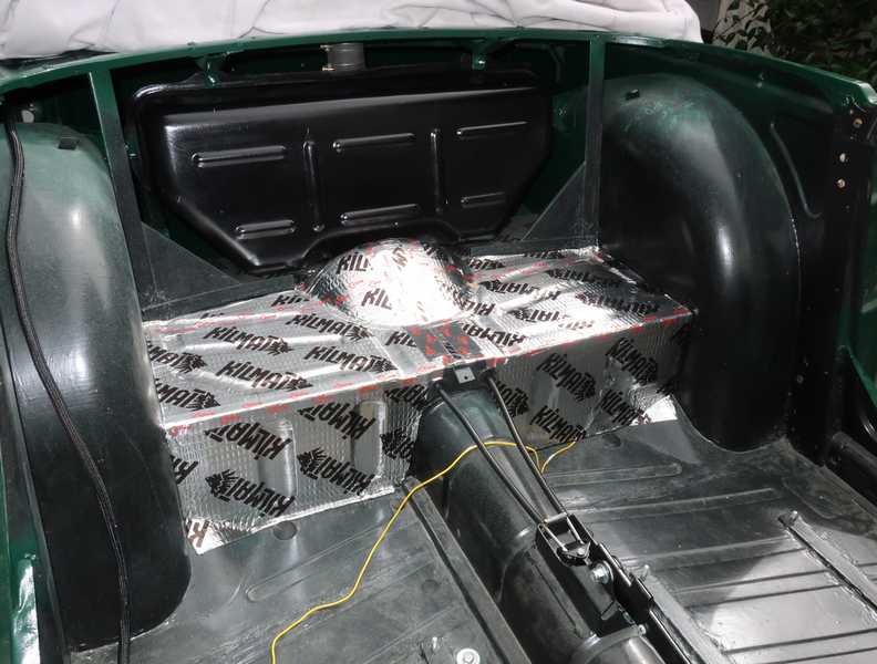
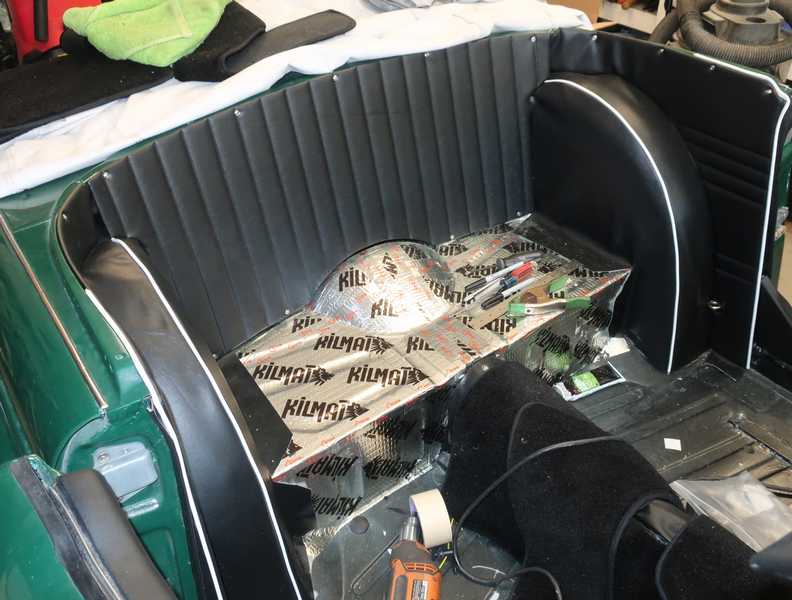
Rear Shelf
The rear shelf originally was covered with some kind of hard rubber material. I have no idea of its purpose. Such materials often were used for thermal or sound insulation, but neither seems likely; it may have been intended to dampen vibrational resonances. In any case, if I left it out, I probably would have learned quickly why it was there, so I replaced it with a more modern material, a tar-like, foil-covered sound and thermal insulation. I did the same for the part inside the trunk.
Transmission and Drive-Shaft Covers
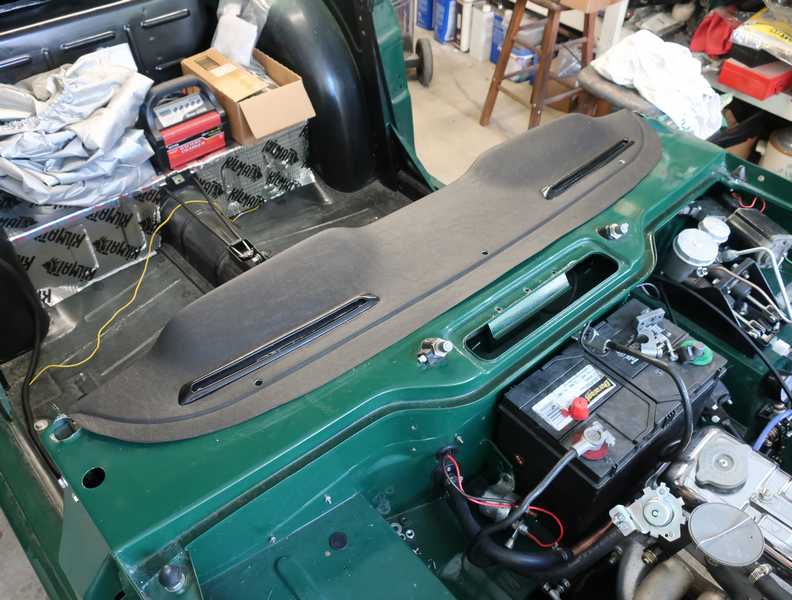
In the picture below, the covers for the transmission and drive-shaft tunnel have been fitted. I installed the shifter console temporarily to check the fit; it had to be removed for the carpet installation.
![]()
The picture shows the standard shift boot, which I decided not to use.
I used the transmission cover that came with the car, an aftermarket part. It was made of fiberglass, while the original was fiberboard. Most of the originals have disintegrated by now. The cover was not a bad fit, all in all, but the mounting holes didn't line up well with those in the floor, and it probably was larger than the original, as the shifter console was a tight fit. It may have been designed for the TR6, with the optimistic expectation that it would fit the TR4/4A as well. The rather thick seal strips between the cover and floor didn't help, and there simply wasn't room for the ones at the ends of the cover, so I left them off.
The installation-hardware kit ($25) was also a waste of money. It didn't contain enough of the special plates, and they aren't necessary, anyway. Screws and large washers work just fine, and, in fact, must be used in several locations, where the plates don't fit. The rest of the kit consists of screws, washers, and captured nuts for the front of the cover, which are cheap and can be purchased anywhere.
The car arrived with the original, fiberboard drive-shaft tunnel cover, which had deteriorated badly. I replaced it with a modern one, apparently ABS plastic (which I could have fabricated easily).
Gearshift and Handbrake Boots
I bought a nice piece of black goatskin leather for new gearshift and handbrake boots. Thin and flexible, just what was needed.
My new carpets did not include a handbrake boot. I used the old one, which was a little tired, as a pattern. The new boot is shown below.
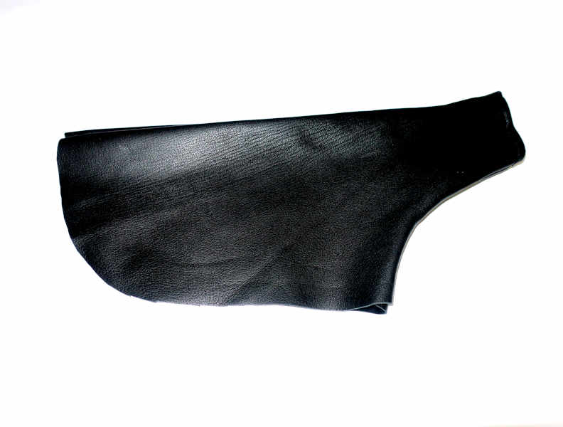
I decided that a leather gearshift boot would look a lot better than the standard, ugly, rubber one. It's a simple cone shape, which required a little measuring but no pattern.
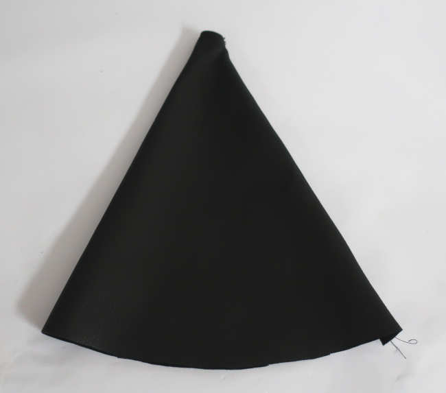
Because the leather was so thin, it could be sewn with an ordinary sewing machine, needle, and polyester thread. To keep everything aligned, I first glued the edges with leather glue, and then, when the glue was dry, sewed them. I used a fairly short stitch length, 1.6 mm.
You can see the boots installed in the car here.
Panels and Associated Trim
Rear Panels and Wheel Wells
Fitting the wheel-well covers is one of the most tedious jobs in restoring any car. Invariably, the cover supplied with the interior kit doesn't fit well, so the job is to finagle it into some sort of acceptable, wrinkle-free condition.
The TR4A originally used a layer of (probably) polyester fiber material to fill the space between the wheel well and the cover, a big improvement over the cotton material that was used in older cars. Today's interior kits include a couple sheets of 1/8-inch-thick foam for this purpose.
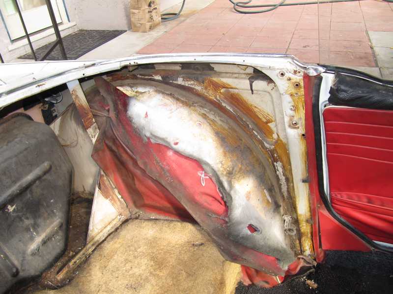
The wheel well has a depression near its top. If that is not filled, the cover will wrinkle easily in that area. The interior kit didn't include anything to fill that depression, and it is not addressed in Roger Williams' authoritative book on Triumph restoration. I fabricated a pad from polyester fill material, shaping it to prevent obvious lumps in the cover's surface. I then covered the wheel well with the provided foam, after trimming it extensively.
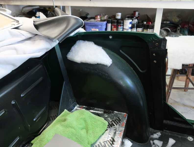
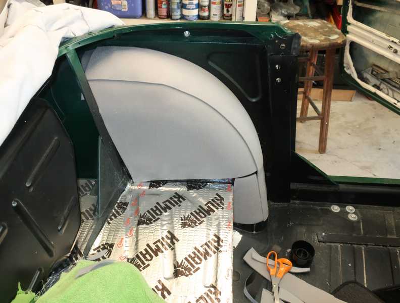
The covers came out OK, I think, which is probably the best you can hope for. If I were to do this again, I would discard the 1/8-inch foam and use the polyester fill for everything. I think that would result in a more uniform appearance.
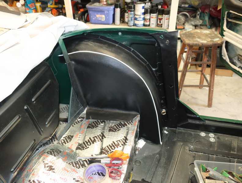
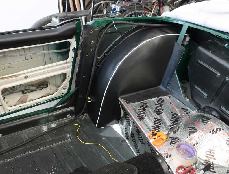
The rear panels needed a little trimming to fit around the wheel wells, but they were otherwise straightforward to install.
Door Panels
I installed most of the rest of the interior before getting to the door panels. Although it's hard to see in the picture below, I covered the doors' inner sides with clear mylar. This is probably not as effective as the original water screen, but it's what most restorers do, and it should at least keep the panel from getting wet and stained.
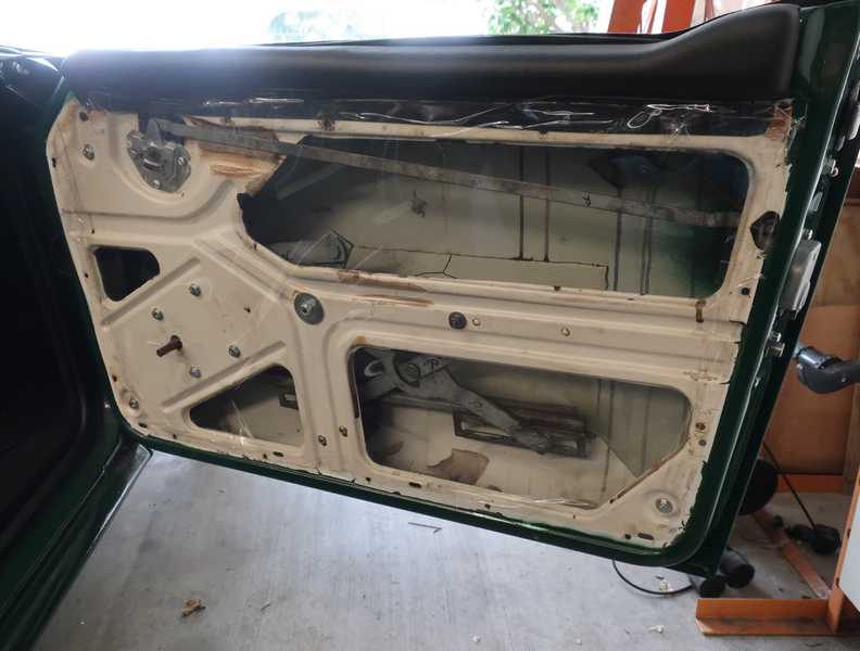
The panels are not completely drilled, probably so they can be used on a couple different TR models; the early TR6 panel, for example, is virtually identical. I had to drill out the holes for the window crank and door lever. Openings in the panel for the door pull and the one screw at the corner of the pocket had been drilled, but the vinyl cover had not been cut for them.
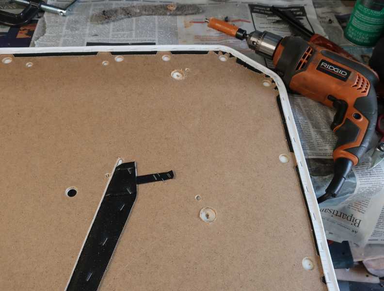
Getting the panel clips aligned is a royal PITA, but the rest of the installation is straightforward. I was pleased that the drillings in the panels were quite accurate and lined up easily with the door. I used new door hardware, of course, since the chrome on the old stuff was pitted. The door hardware is surprisingly inexpensive.
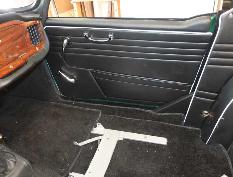
Below, all the panels are installed. The console, carpet, and steering wheel had been installed before the door panels. In the picture below, you can also see the leather boots I made for the brake lever and shifter. The seats, at this point, were almost finished; I was waiting for some seat parts to be delivered.
Carpet Installation
I bought the "Deluxe" carpet set from Victoria British, as I suspected their "Standard" kit to be similar to the cheapo carpets sold on eBay. It was indeed better quality than the eBay kits, but not a lot better. Like the carpet set I bought for my MG TD, many of the edges were unfinished. To prevent them from unraveling, I singed the edges with a flame. The piece that covered the center of the drive-shaft tunnel did not have a cutout and boot for the hand brake. The boot supplied with many carpet sets, however, is thick and ugly, so this seeming annoyance still allowed me to make a better-looking boot.
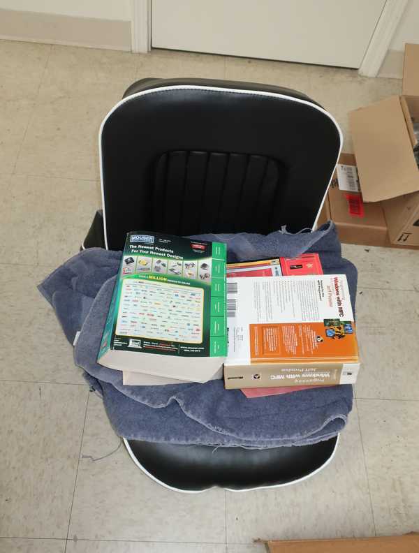
The carpet set included quite a few pieces, so I laid them out on the floor of my office to figure out where they all went. Some already had insulating pads, some not, for unclear reasons.
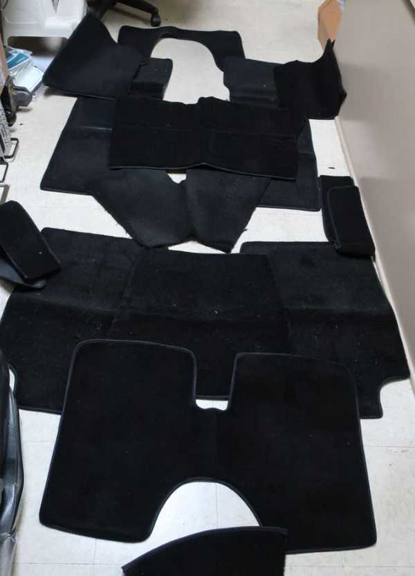
Once I had figured out what went where, I set the carpet pieces loosely into the car, so I understood how they fit together.
It's possible to find plenty of information on carpet installation, but it's mostly obvious. I found that it's probably better to start at the outside and transmission tunnel and finish with the floors and rear shelf, but even that is not essential. The job requires care, but isn't particularly difficult.
Many people glue all the carpet pieces, but it's much better to install snaps on pieces that might be removed. Once the carpet pieces were glued, peeling them back often damaged the backing. Some, such as the floor pieces under the seats and the rear tunnel cover, are held in place quite well by other interior pieces, so no snaps or glue are needed.
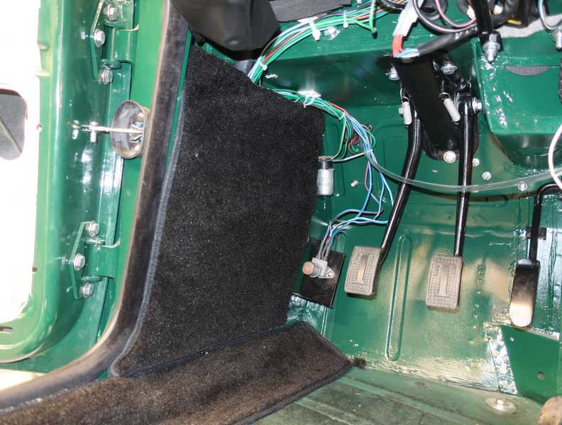
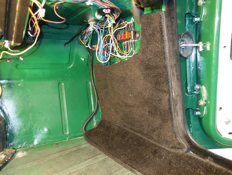
Many of the carpet pieces had to be trimmed, especially the panels on the sides of the footwells, shown below.
The sill pieces were among the first installed.

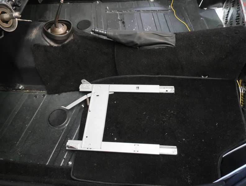
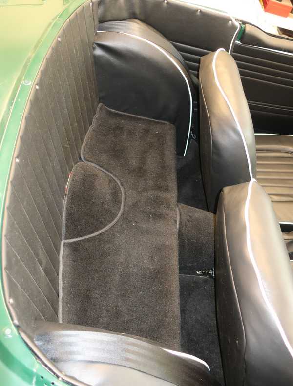
The transmission-cover piece shown below was glued; the forward one was not. The carpet piece including my leather handbrake boot didn't really need any glue or snaps, but I still added one snap in the rear. The floor section shown below was held in place by the seat slide. I had to trim away the felt backing, being careful not to damage the carpet; it took a lot of painstaking work with scissors and a sharp knife. In some carpet sets, the backing is supplied separately, not glued to the carpet; I would have preferred that.
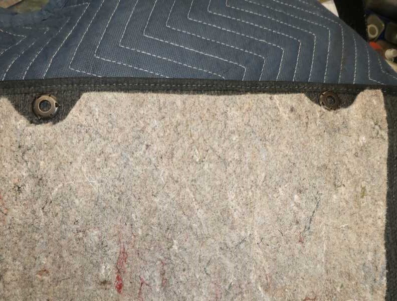
The backing, which was about 3/8 inch thick, also had to be removed for snaps. Below, snaps on a front floor section.
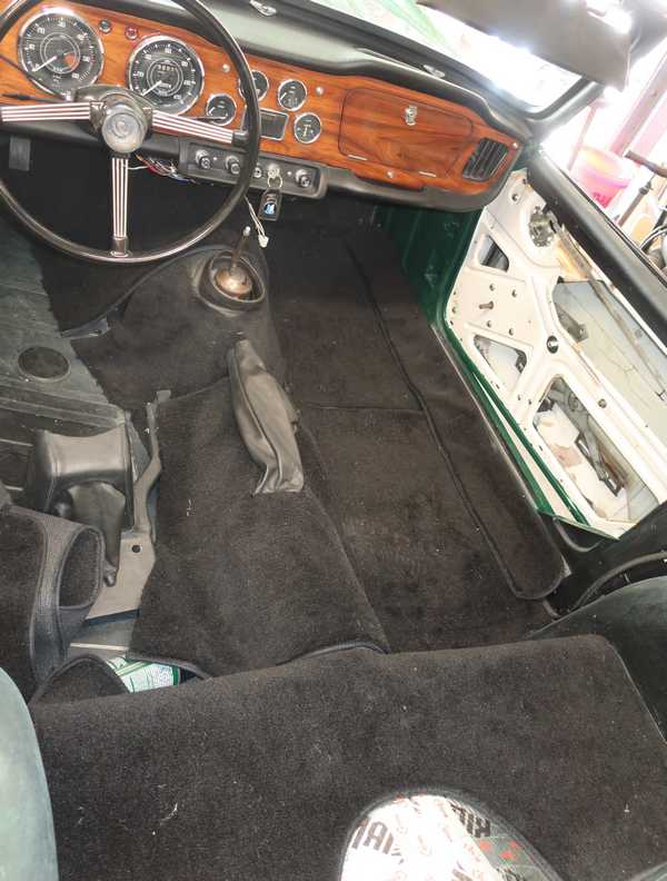
Below, the carpet is installation is complete. The shifter console has also been installed.
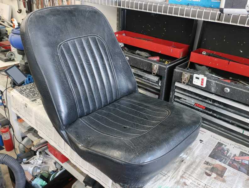
Seat Restoration
The seats of various TR models are all different, so restoration instructions for one model are not terribly useful for another. I found only a couple sets of instructions for rebuilding TR4A seats; the best by far is linked here. My seat restoration followed that document closely. Roger Williams' book, How to Restore Triumph TR2, 3, 3A, 4, and 4A, was of limited help, as the pictures weren't very good and the seat kit used in his example was quite a bit different from mine.
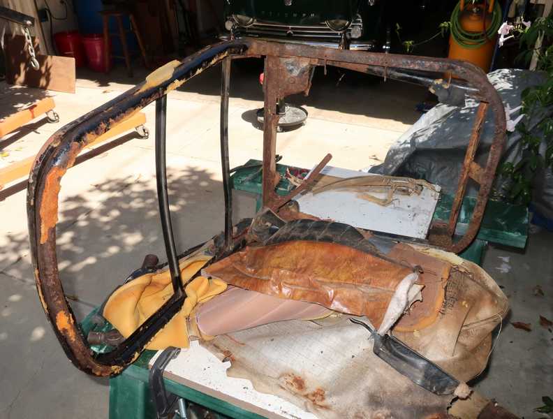
Tear-Down
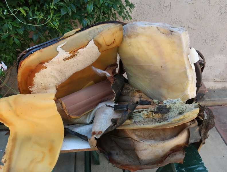
Restoring a pair of TR4A seats is something of a rite of passage into Triumph adulthood. Superficially, the seats seemed decent, but in fact they were in bad shape. Restoration was imperative.
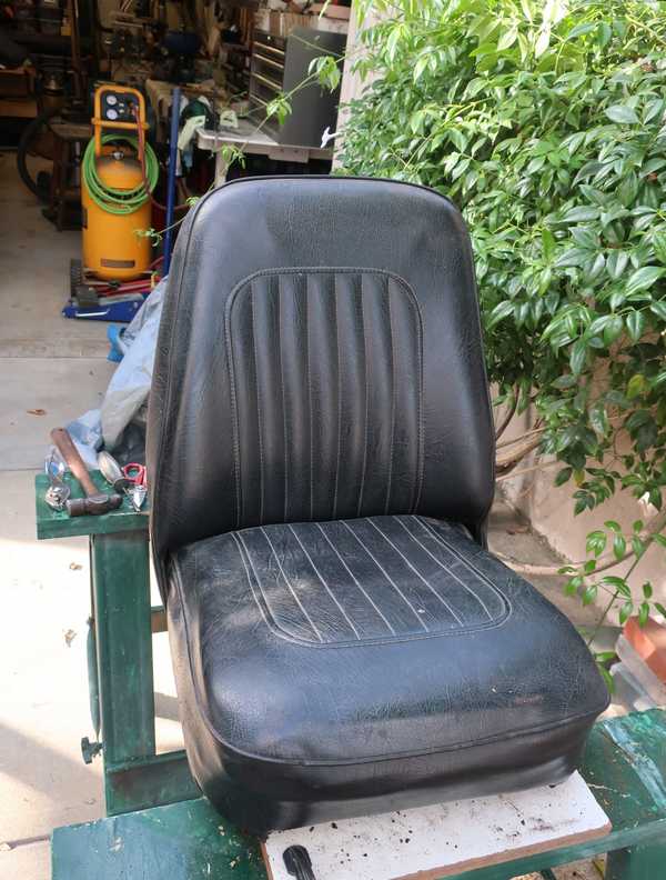
Problems were evident as soon as I started to disassemble the seats. In this seat, the diaphragm had cracked so badly that someone used elastic cords to hold it in place. In both, the rubber seat-back straps, probably original ones, had sagged and hardened.
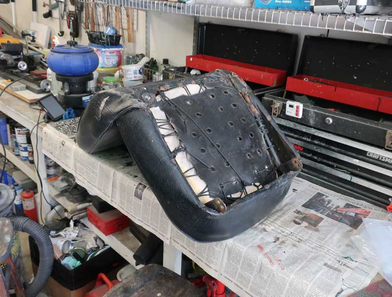
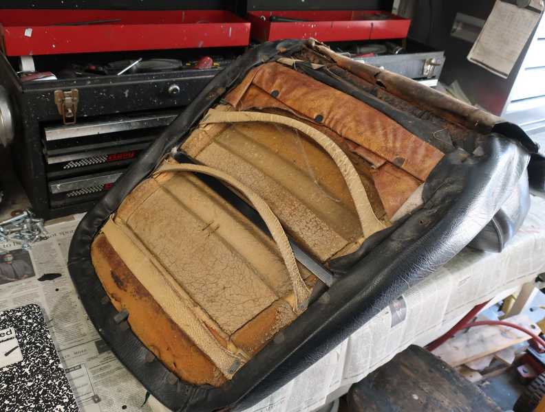
Tearing down the seats showed how they went together. I took a lot of pictures, but they were less useful than I had hoped; the new covers and their installation were significantly different from the old ones.
Frame Restoration
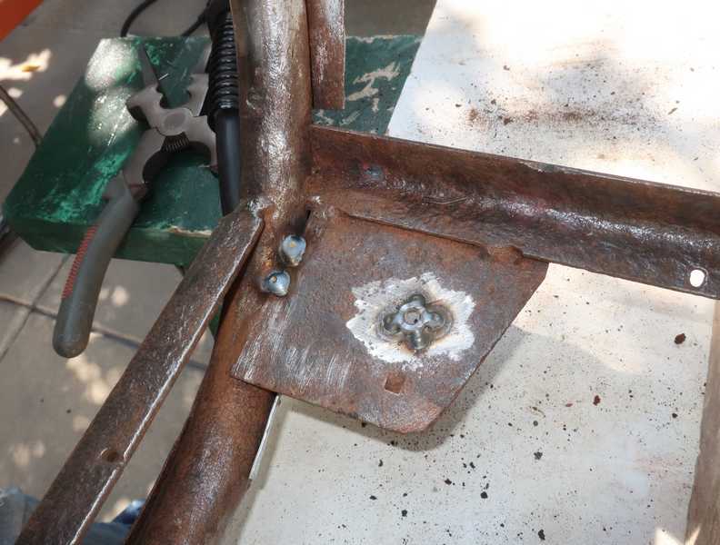
I cleaned the frames in the usual manner, removing as much rust and old paint as I could, and made some simple repairs. In one seat, the screws for the rubber seat bumpers were rusted into their captured nuts, so I had to grind off the nuts and replace them. While I was at it, I added a couple more welds to strengthen the plates, as they support the occupant's full weight. I also replaced two of the plates on the undersides of the seat rails; one was badly rusted, and the other completely gone. One of the seat-back stays was bent and had come loose; it was easy to fix.
It's a good idea to check the seat frames carefully for cracks; I'm told that they are not unusual. Fortunately, I didn't find any in mine.
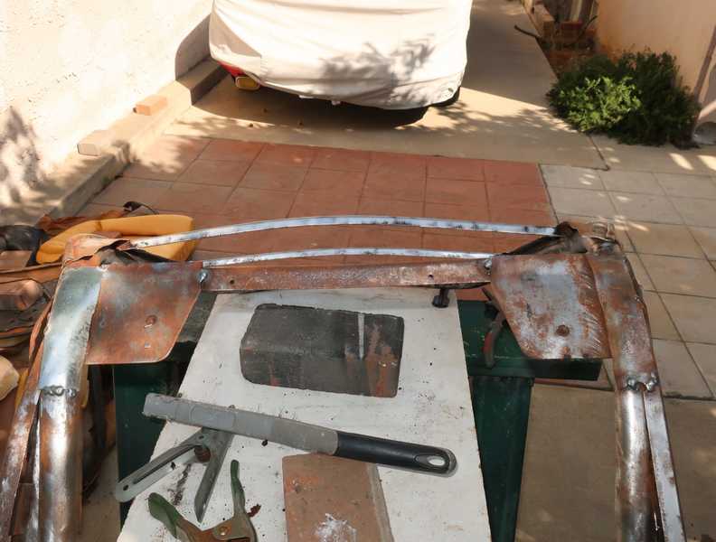
Each seat had one 11-inch-long spring stretched between its main rails. Its purpose is to hold down the rear of the base seat cover; the end of the seat-base fabric is wrapped around it. The new covers have a sleeve through which the spring fits. The existing springs clearly were goners, and new ones were not available. I bought a selection of springs from McMaster-Carr, and eventually found something I could use.
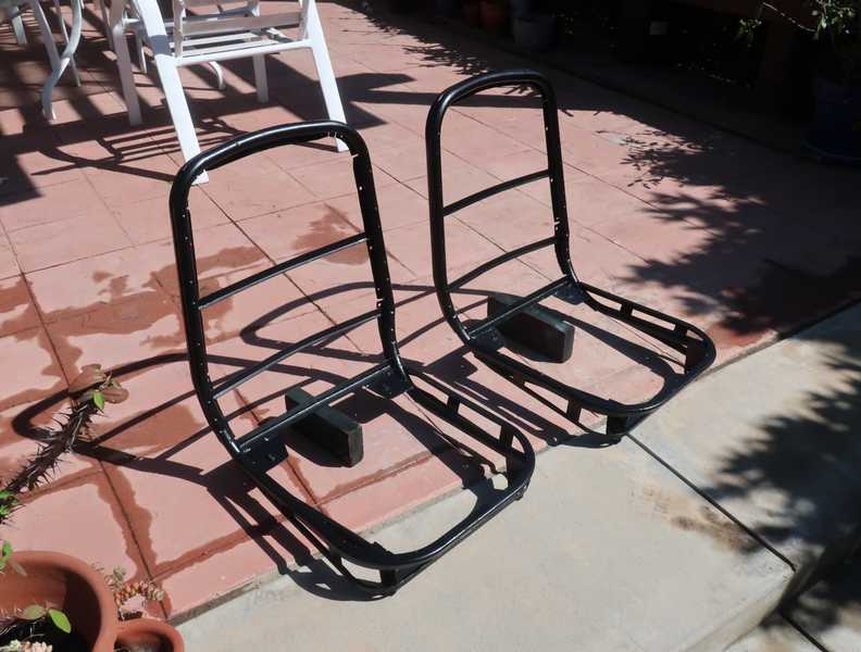
I gave the seat frames a coat of rust-encapsulating paint, then sprayed them with the same black Rustoleum I used elsewhere in the car. The rust encapsulator probably would have been enough to protect the frames against rust, and appearance obviously was not important. But I just felt better with fully painted frames. They were a little more protected from nicks and scratches that might have occurred as I worked on them.
Below, the restored seat frames, sitting on the warm patio to cure the paint.
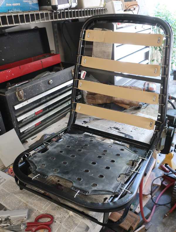
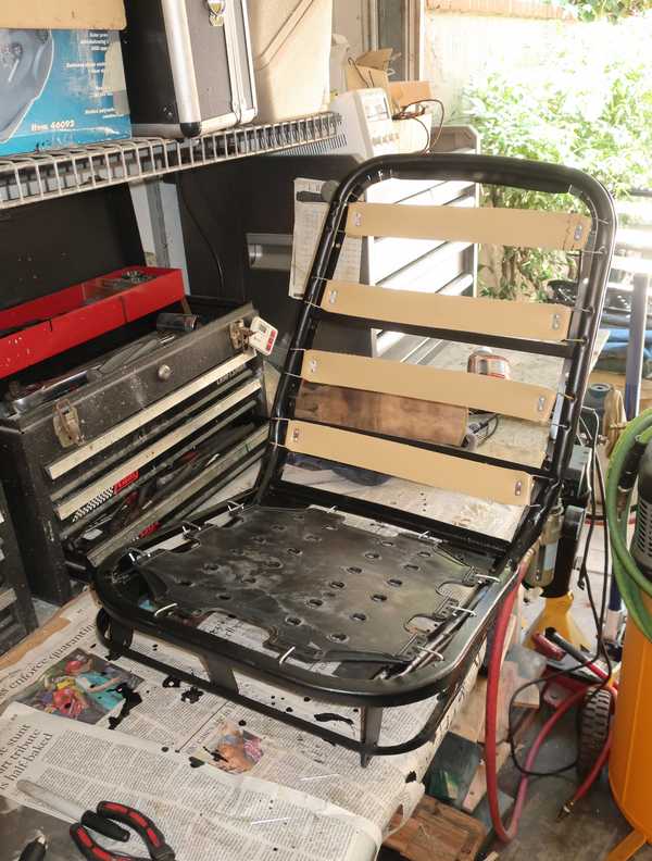
Straps and Diaphragms
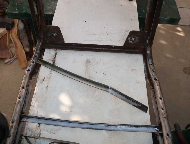
The first step was to install the rubber seat diaphragms. Until this point, I hadn't noticed that the rearmost attachment holes in the driver's-seat frame had worn almost all the way through. The hole locations are not critical, so the easiest fix would have been to drill new holes adjacent to the old ones. However, since the metal in that rail had been thinned by rust, I thought it best to weld on a reinforcement. I had to wire-brush off some of my nice, new paint; weld; redrill the hole; and repaint.
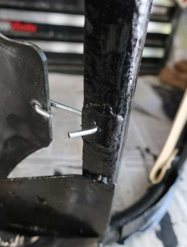
I bought new Pirelli-rubber strap material for the seat backs but reused the hook wires and plates. I attached them with pop rivets. The original straps were two inches wide, but I could find only 2 1/2-inch material; I tapered the ends to fit the original hooks. The wider material fits perfectly well, and one could make the case that the extra width is advantageous.
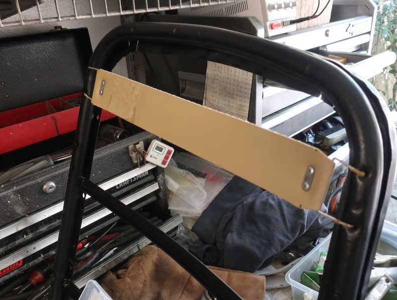
The straps are a little tricky, because the Pirelli material, which is just a fabric-reinforce rubber, stretches only 1/8 - 3/16 inch over this length. The straps therefore must be cut precisely, but also must be tight, so they don't sag or come loose. There is only about an eighth of an inch in length between too loose and too small to fit.
Below, the two seats with the straps and diaphragms installed.
Seat Upholstery
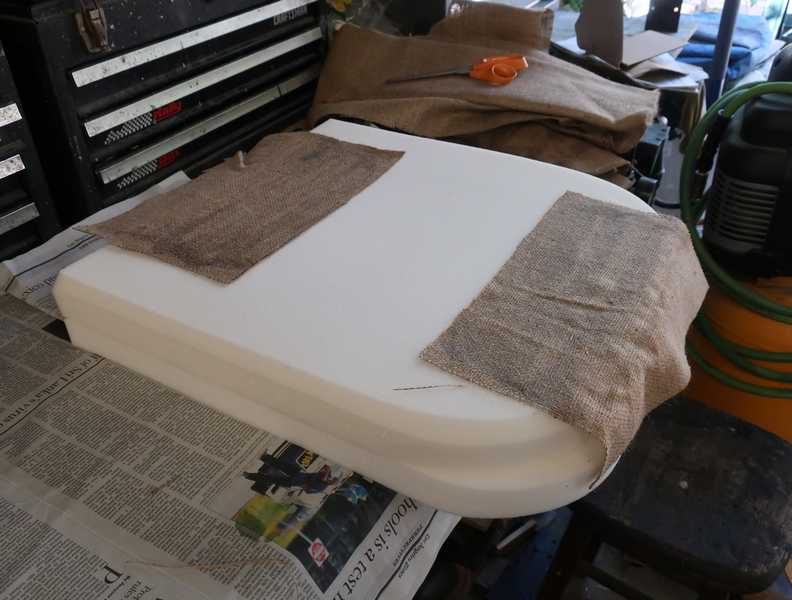
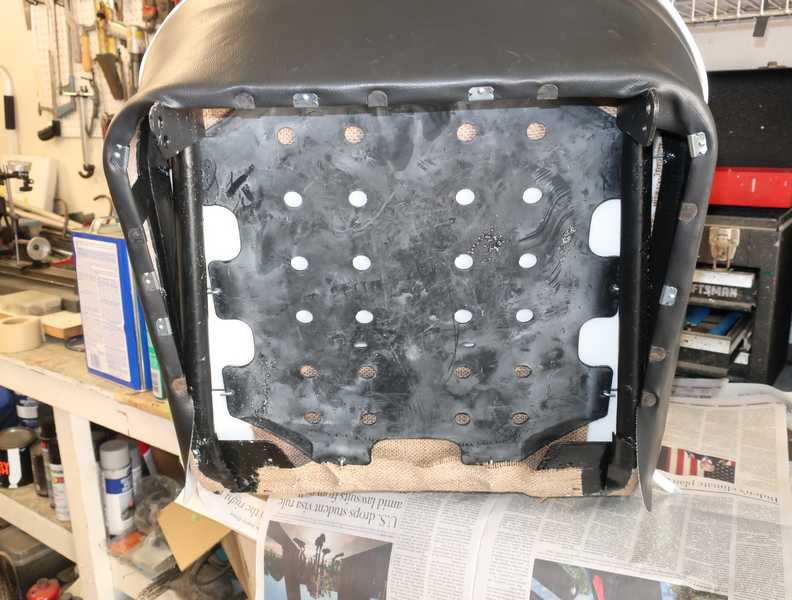
It is necessary to wrap burlap around the base of each frame. The burlap is an essential support for the sides of the seat bases.
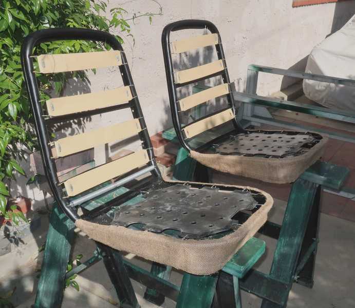
The two pieces comprising the bottom foam were glued together, and two pieces of burlap were glued to the underside of each foam assembly. Those burlap "flaps" were glued to the seat rail in back and to the existing burlap in front, attaching the foam to the frame while leaving some freedom for it to squirm a little, as needed to accommodate a typical, 250-pound American ass. A piece of foam wrapped the lower part of the frame smoothed it all off.
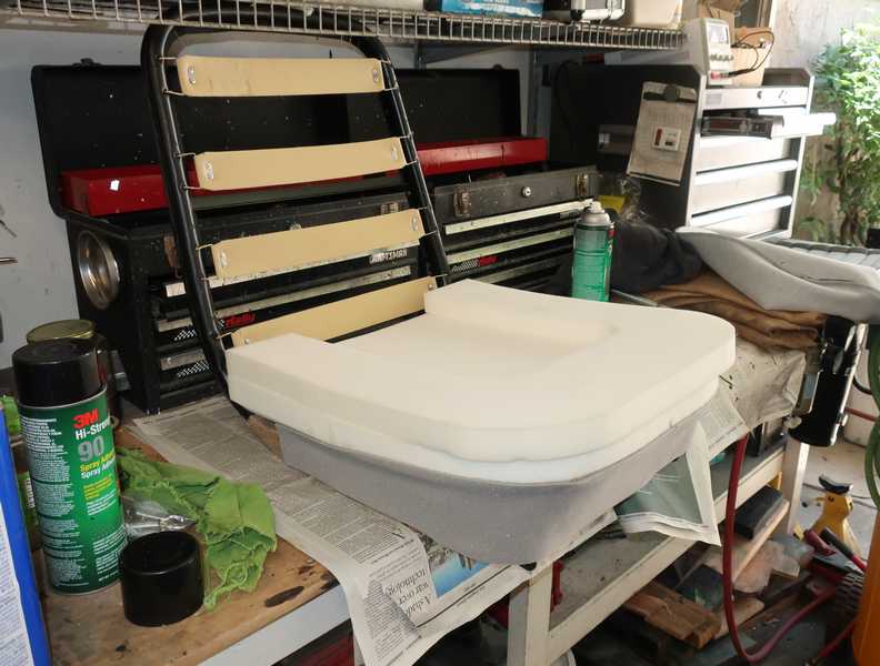
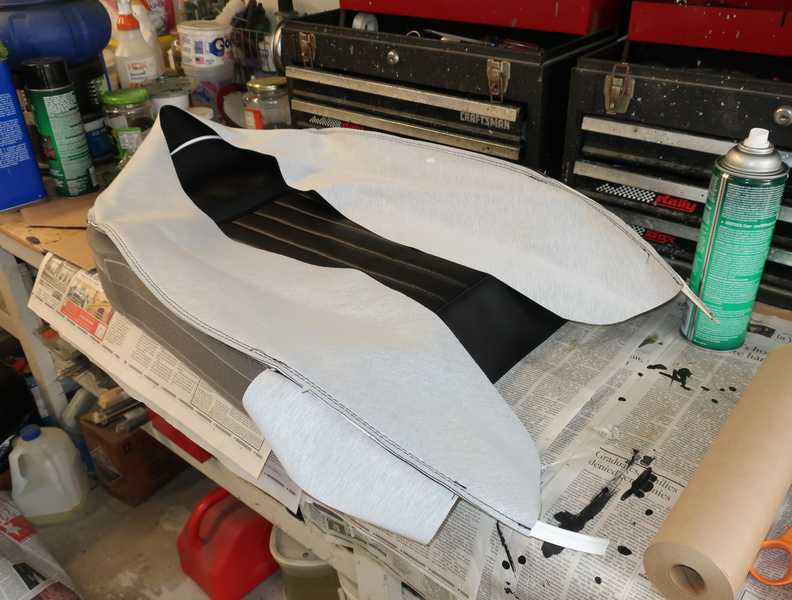
The seat cover was then installed, glued to the foam only along the edges of the pleated panel. Pulling it around the foam and the frame looks easier than it was.
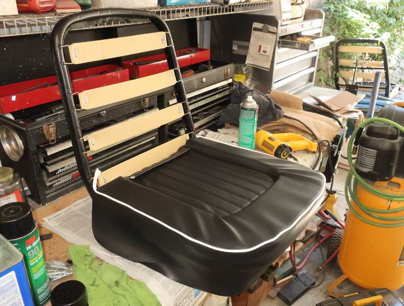
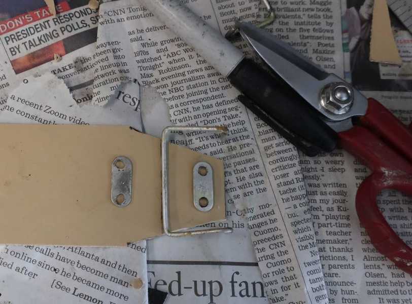
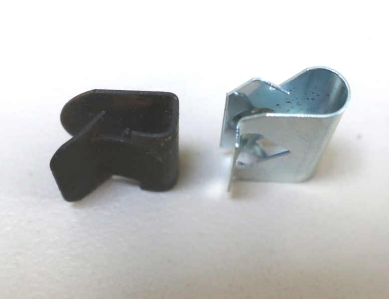
I found some clips on eBay to augment the ones I saved from the old seats. The galvanized clip shown below is the new one. I used a few of each type of clip to attach the fabric to the seat rail. This took out the wrinkles visible in the picture above.
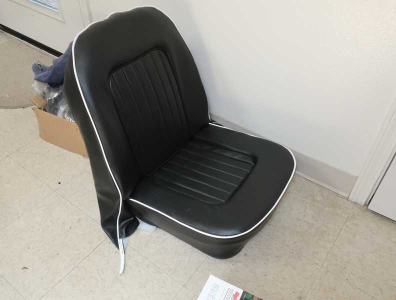
With the vinyl fabric pulled tight over the foam and clipped to the frame rails, the seat base was finished.

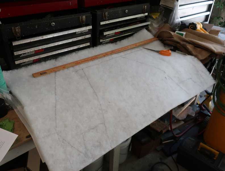
The seat back required a "hood" cut from polyester batting. I drew the hood on a 24" x 40" piece of batting, cut it out, and glued it to the seat frame.
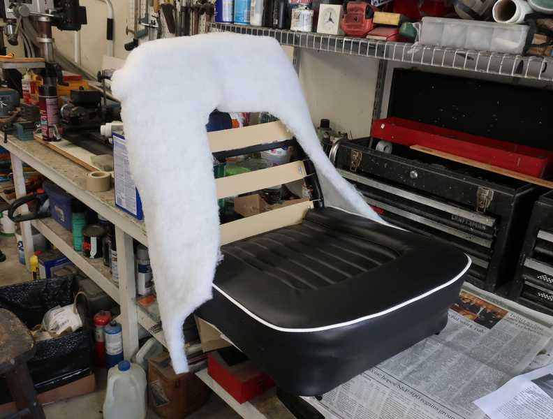
The seat-back foam, with the seat cover glued to it, was pushed up under the hood. The sides of the cover were then folded over the foam and temporarily secured to the frame by clips.
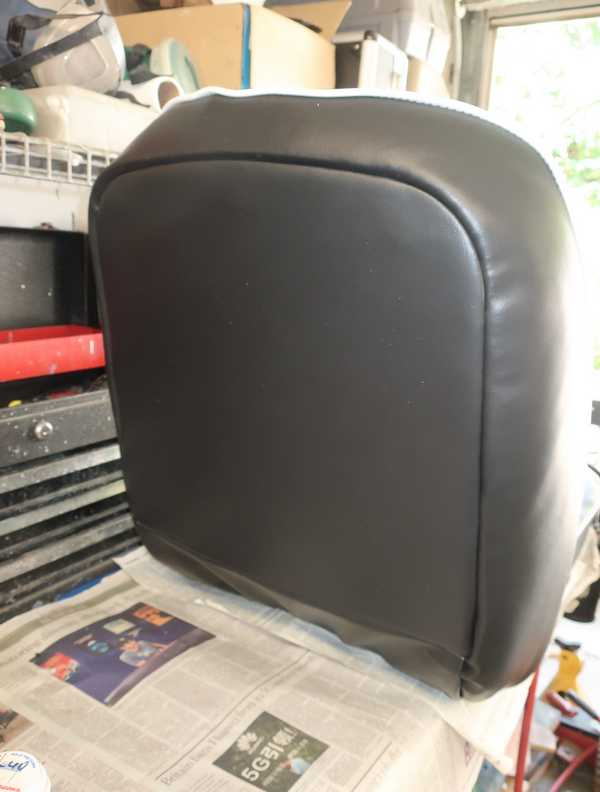
Because the foam piece was longer than the back of the frame, it initially bowed outward. Setting the seat flat overnight with a little weight on its back made the foam take a new set.
Installation of the back panel, which was largely straightforward, completed the seat.

Seat Belts
I bought nice-quality, three-point seat belts for the car. Locating the mount points for the shoulder straps was a bit of a dilemma; ideality, they should have been located at the tops of the wheel wells. In that location, however, the mounts might have interfered with the lowered soft top, so I mounted them on top of the wheel well just behind the rear panel. The other two mount points, of course, were the factory lap-belt mounts.
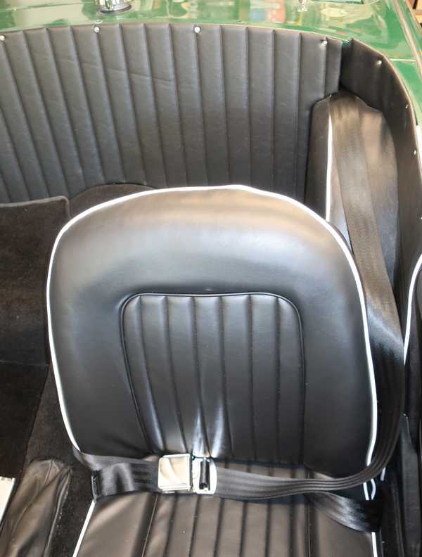
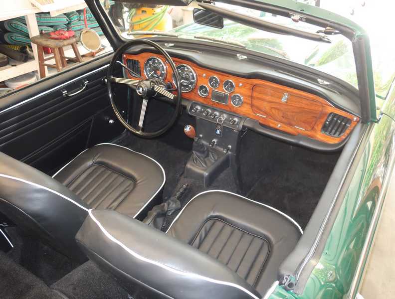
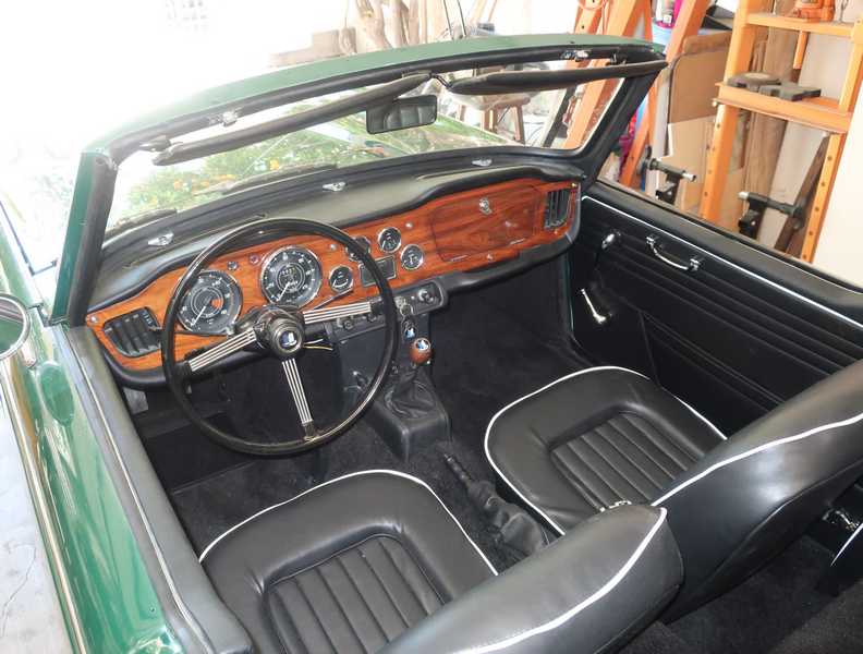
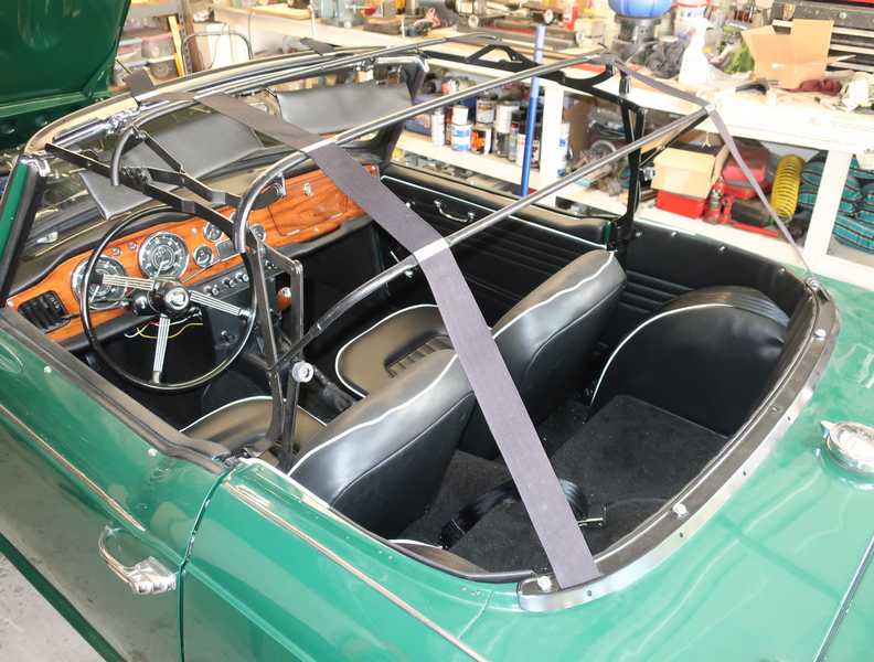
I tried out the belts; they felt really good. I finished the second seat and seat belt; below, the two seats, installed in the car.
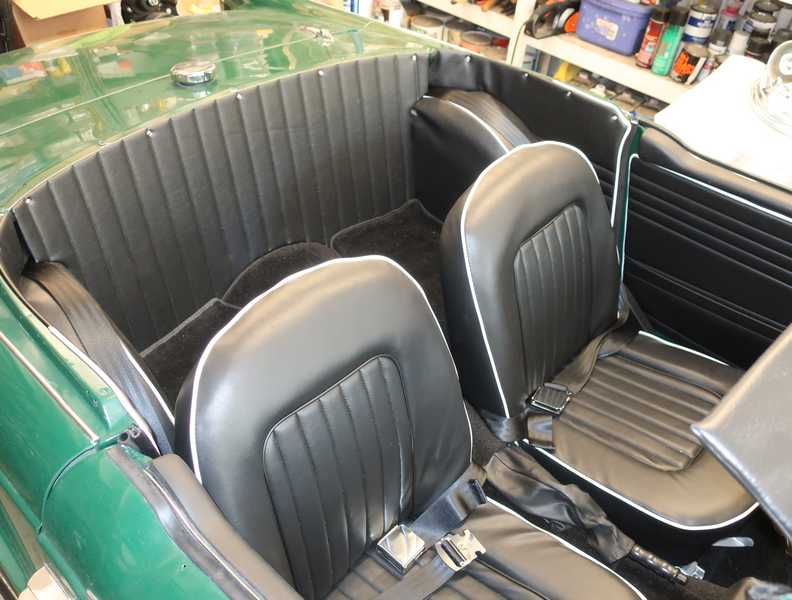
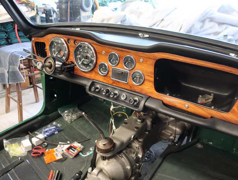
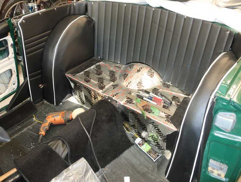
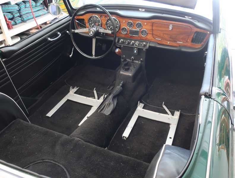
Two views of the completed interior.
When people photograph cars, they always seem to show only views looking toward the front and neglect a view of the rear. So, to end that tradition, here's a view of the rear part of the interior.
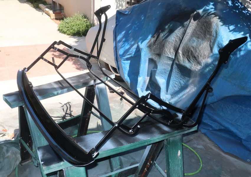
Soft Top
The best information I found on soft-top installation was in Roger Williams' book, How to Restore Triumph TR2, 3, 3A, 4, and 4A. I found a little useful information on-line; probably the best was on the Buckeye Triumphs site; it seemed to be based on an article on the Vintage Triumph Register site. That document is for TR6s, though, not TR4As, but much of it is still relevant. The TR4A top is very different from the TR4, so TR4 information is not useful.
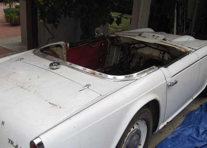
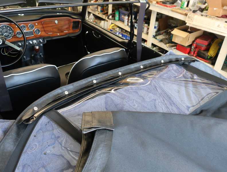
One difference between the TR4 and 4A tops is the way the rear edge of the top is mounted. On the TR4, it is held on with lift-the-dot (LTD) fasteners and an aluminum trim piece, so the entire top can be removed completely, while the TR4A uses a retaining bar and a non-removable top. At some point, the retaining bar on my car was replaced by a TR4-style set of LTD fasteners and trim. It's hard to understand why that was done. The mounting holes for the retaining bar were in place, though, so I sourced the parts and returned it to the correct, 4A, setup. Below, the TR4-style trim strip on the car, as I received it.
The soft top that came with the car was not in good condition. It was torn, dried out, and drab looking, and three years of outdoor storage hadn't done it any favors.
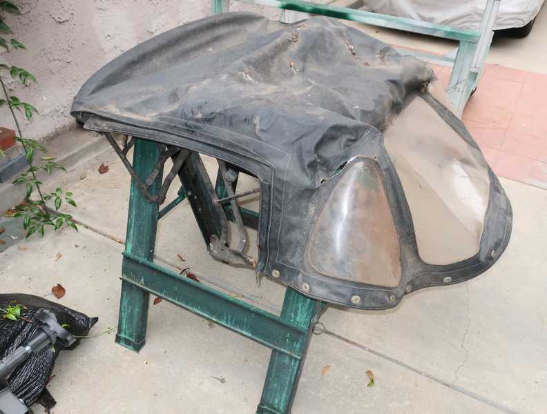
I removed the top from the frame, then inspected the frame and cleaned it. The frames are often bent, and that prevents the top from fitting as it should. Fortunately, this one was OK. The frame was painted black at some point, probably when a top was replaced. Originally it would have been beige. You can see a little of that color in the second picture, below.
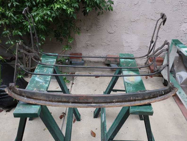
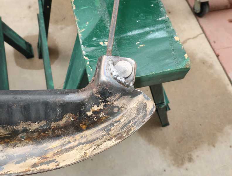
It did, however, have a fatigue crack in the front rail near one of the mounting rivets. I welded it; a simple fix. I once saw an identical crack on another car, so this might be a common problem.
I cleaned and sanded the frame, primed it, and painted it with semigloss black Rustoleum, the same paint I used for the frame and other black body parts. I saw no need to try to duplicate the original color. When the paint had cured completely, I installed it on the car with new, generic bumpers, which are probably better than the overpriced ones from the usual parts suppliers.
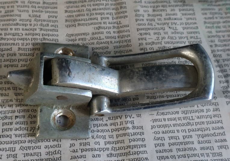
The hood latches were well worn (first picture below) so I had them replated. They're an important accent in the interior. They had to be disassembled for plating, but the hinge pin was easily removed.
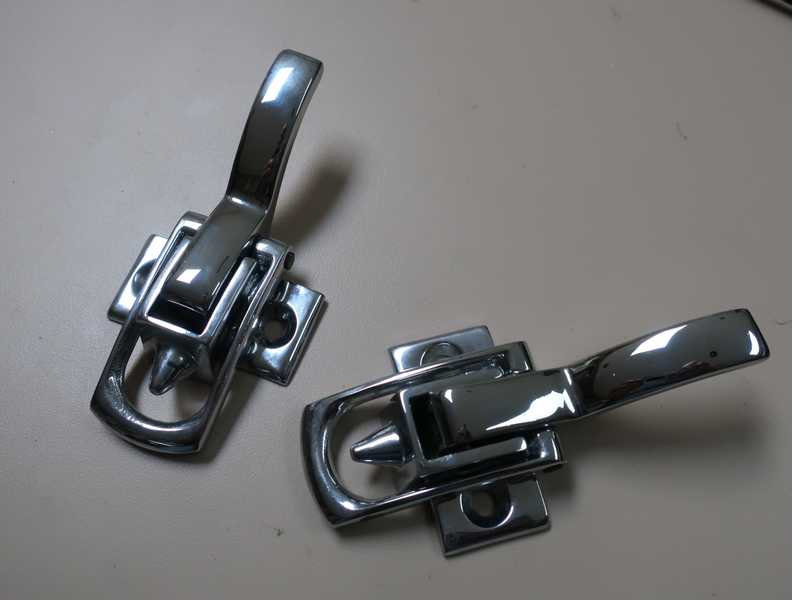
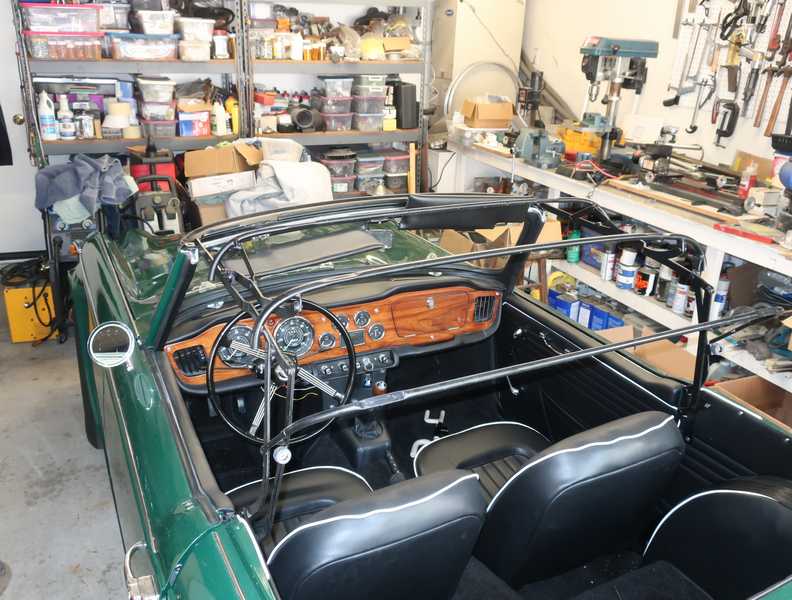
I installed the latches on the top and window frames. Fitting the new convertible top requires this.
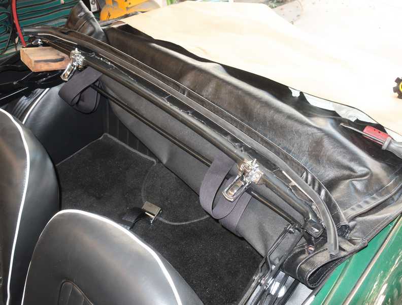
Next step was fitting the straps to the frame. The rearmost bow has no fixed position, so I determined it by setting the new top over the frame. The straps were then riveted to the frame.
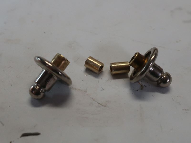
The rear edge of the top is attached to the retaining bar by a row of seven LTD fasteners. Their bases act as rivets to retain the top, and their pointy ends are attachments for a tonneau cover or a boot that covers the lowered top. The fasteners are normally inserted through the rear edge of the top and the rail; then they are peened like rivets to hold the whole assembly in place.
I didn't like that arrangement, as the fasteners were awkward to install, there was no ordinary tool to install them, and I was not convinced that they would hold well. Instead, I made threaded inserts, so the fasteners could be held in place by screws; I soft-soldered the brass inserts into the fasteners. The end of each fastener had to be shortened by approximately 70 mils, or its protrusion would have prevented tightening the back-up washer against the rail.
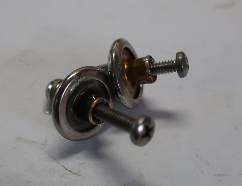
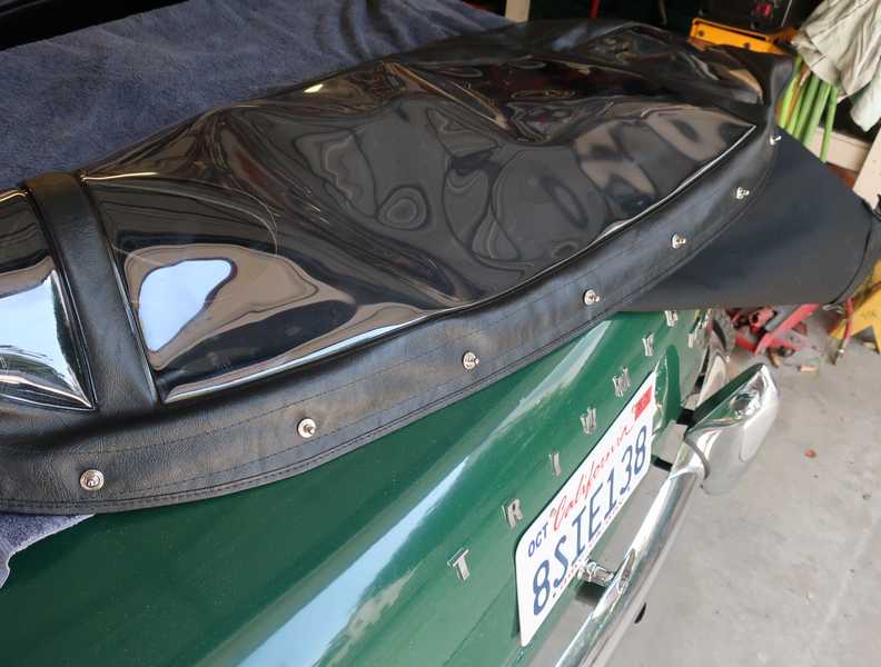
Below, the top has been installed on the rail with the LTD fasteners.
The front edge of the top has a weather seal with a stainless-steel retainer. Its rivets and some glue attach the front edge of the top to the frame.
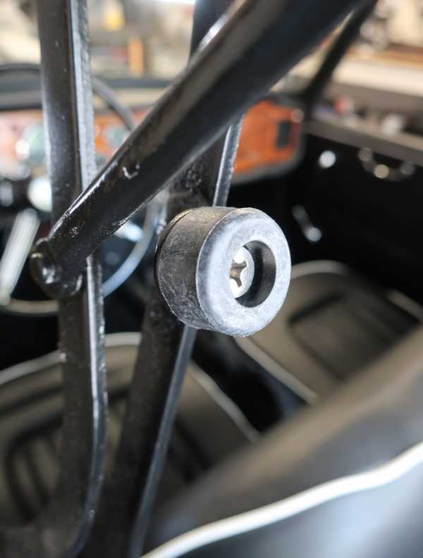
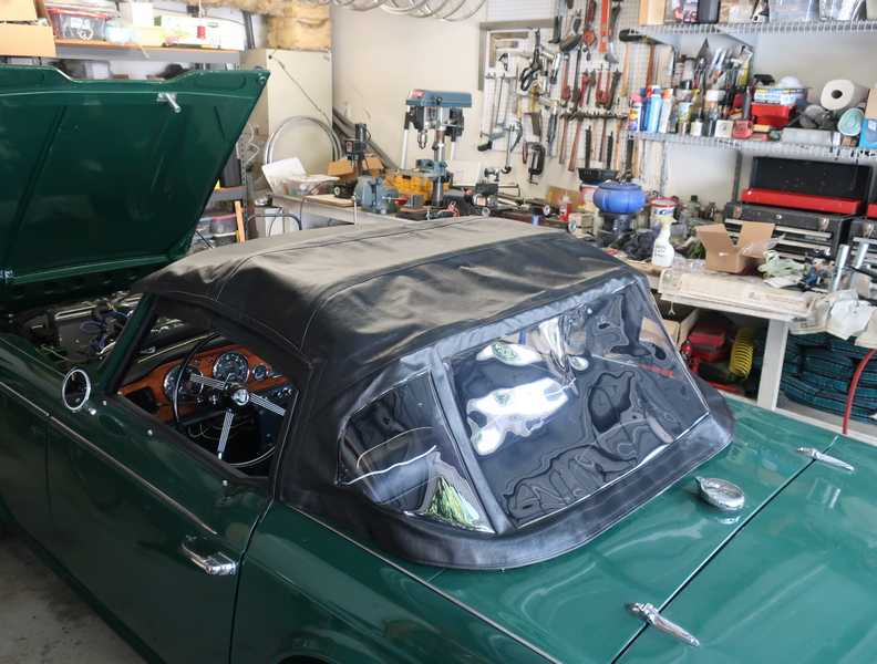
Below, the finished top. The lower edge of the side-window panels is held down with snaps, which are not terribly strong. I wasted a lot of time trying to find a set of snaps that was stronger than the ones from the car-parts suppliers; I found some that were a little stronger, but not really good enough. In the end, I put the male half of each snap in a vise and squooshed it a bit, making it about 15 mils wider. That sounds a little brutal, but it fixed the problem.
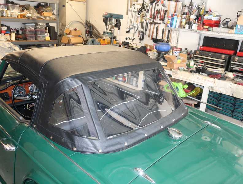
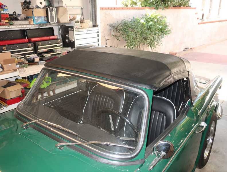
Although it's not a perfect installation, I'm still happy with the appearance. The top fits tightly, in part because I took Roger Williams' advice and installed the front edge 3/8-inch short of the point that I'd measured. The top initially was very tight, but soft tops always stretch out a surprising amount over time. After a couple weeks, the top was perfect: it fit snugly and was not difficult to close.